This thread has been locked.

If you have a related question, please click the "Ask a related question" button in the top right corner. The newly created question will be automatically linked to this question.

LM2903B: lm2903b output when Vcc drops to 0

Part Number: LM2903B

Hi Team,

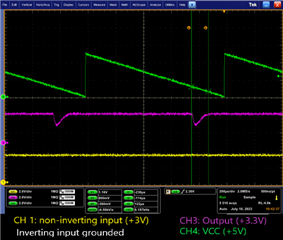
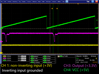
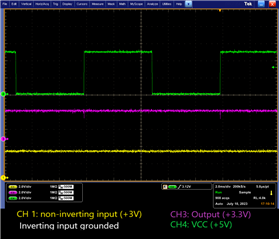
My customer is using LM2903B and finds below issue.

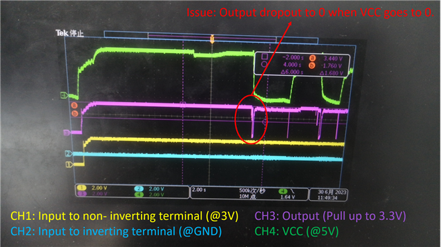
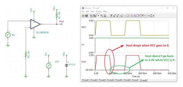
From my understanding, the output transistor won't be conducting at Vcc=0V, so the output would be whatever voltage the pull-up resistor is tied to, i.e., 3.3V. So, why there has a dropout when VCC goes to 0? And when VCC becomes 0, the output is normal 3.3V.

I tried to simulate this in Tina, the sim results is similar that output has a dropout when VCC goes to 0. But there has a difference that in simulation, the output doesn't go back to 3.3V (it keeps 0V) even VCC is stable 0V. I don't know why.

 1234.LM2903B.TSC

Could you help explain how this issue happen? and why there has different results in Tina? thanks a lot.

Best regards,

Yang

  • Hi Yang,

    Thanks for your post. I have acknowledged your question and will get back to you tomorrow. 

  • Yang

    Thanks for your post.  Looking at the provided waveforms, I think the the reason why you are seeing the glitch has something to do with the ramp down rate of the VCC.  We will try to emulate in our lab but that is my thought.  In regards to the TINA simulation, the model just isnt' designed to reflect that sort of use case.  I will get back to you with what we see on our bench by the end of the week.  In the meantime, I really don't understand your use case and why you want to keep cycling the power on the comparator.  If you wish to share more on your application, maybe we can find a part better suited.

    Chuck

  • Hi Chuck,

    thanks for your help. 

    In the meantime, I really don't understand your use case and why you want to keep cycling the power on the comparator.

    -> I just use PWL to simulate customer's case of power up & power down.

    Let's wait your reproduce experiment.

    Best regards,

    Yang

  • Thanks Yang for following up. I understand you using simulation but I would like to understand more about the customer's use case, especially why they need to power cycle as shown in their waveform screencapture.

    Chuck

  • Hi Chuck,

    Let me clarify, in customer case, there has no power cycling, just power up & power down one time. I use powering cycling in my simulation just want to make sure no simulation difference between 2 cycles. Will you check it in the lab this week. I can't check it because I don't have samples on my hand.

    thanks a lot.

    Best regards,

    Yang

  • Hi Yang,

    I have been working in the lab on behalf of Chuck to recreate your setup. When ramping the voltage supply, between ~1.1V through ~600mV I’m getting the drop on the output voltage. Operating for a long time below 2V (the minimum operating voltage) is definitely causing issues on your output. Ramping your supply voltage much quicker will clean up your output. Also, adding a resistor with a capacitor on your output would add delay and could resolve your issue, but we do not recommend this.

    Best,

    Michael