A related question is a question created from another question. When the related question is created, it will be automatically linked to the original question.
If you have a related question, please click the "Ask a related question" button in the top right corner. The newly created question will be automatically linked to this question.
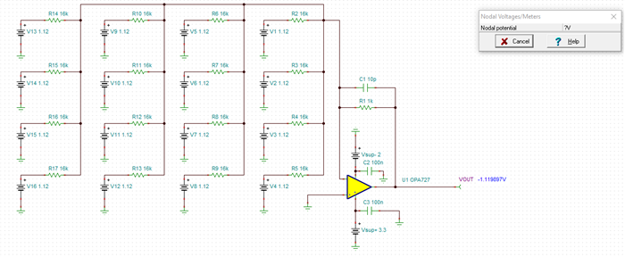
The gain for each input is RF / Rx = 16k / 1k = 16V/V. If I understood correctly, each input V1-V16 is +1.12V. The total ideal output will be at 16*16*1.12V = - 286-V/V.
The op-amp is powered by VS(-) =-2V and VS(+) =+3V, hence the amplifier output will be out of range, in the negative rail.
Perhaps you meant, RF = 1kΩ and R1..R16 = 16kΩ ?
Kindly let me know if I misinterpreted the input voltages, or misunderstood the circuit.
Yes, as shown above, the summing amplifier with RF = 1k, and R1..R16 = 16k, and assuming R20 and R21 on the negative supply connection are unpopulated, the circuit will work with input signals at V1..V16 = +1.12V. The output will be around ~-1.12V. You could add a small feedback capacitor for stability.