This thread has been locked.

If you have a related question, please click the "Ask a related question" button in the top right corner. The newly created question will be automatically linked to this question.

JFE2140: JFE2140 Datasheet: I desire to know the value(s) of capacitors CS and CS2 of figures 9-5 & 9-6.

Part Number: JFE2140

Dear Sirs at the Support Team,

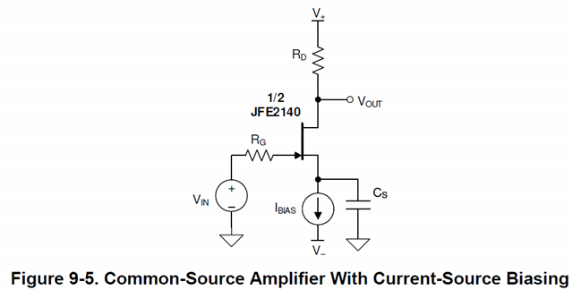
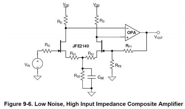
Referring to the JFE2140 Datasheet, in the schematic of fig. 9-5 (page 14), there is a capacitor (CS) in parallel at a current source Ibias. In the schematic of fig. 9-6 (page 15), there's the cap CS2 in parallel at source resistor RS2. I would like to realize one of the two schematic using a current regulating diode SST511 to set the DC bias and to reduce the noise even more. Could you tell me the capacity values needed for CS and CS2 since not present in the part-list?
Thanks so much for your kind attention.

Kind Regards,
Enrico Borsetti

  • Hi Enrico, 

    The component values are highly dependent upon your design and come with trade offs. In particular you can see with the setup below I simulated a design that biases the JFE at 2 mA with a VDS of 3.67 V. I swept the capacitor that is used for filtering on the source node and in parallel with the source resistance of 280 ohms. The corner frequencies are determined by 1/(2*pi*R*C). The larger the capacitor the lower the noise. This can be seen in the figure below comparing Vout 1 to Vout 2 and 3. The biggest noise benefit can be seen using the 100 uF capacitor. This will come with a trade off on initial power up to fully charge the capacitor before the design is fully dc biased. In this case the capacitor needs to charge through the 4k resistor from the power supply. The concept is the same in both circuits above. I have attached my simulation below. I hope this helps clarify on choosing component values for your design. Let me know if I can be of further assistance. 

    JFE CKT.TSC

    Best Regards,

    Chris Featherstone

  • Dear Chris,
    Thank you very much for the quick response and simulation with attached graph. Since I have several J511/SST511 in the drawer, could you simulate another graph by replacing the resistor with a J511 and cap in parallel? I thank you for your kind collaboration.

    Looking forward to hearing from you soon,
    Enrico

  • Hi Enrico, 

    I don't have a model for the J511. If you happen to have the model can you provide it? We offer Tina Ti as a free download here:

    https://www.ti.com/tool/TINA-TI

    Best Regards, 

    Chris Featherstone

  • Hi Chris, I don't have it as well. I just wrote to Linear System and InterFET asking if they have it available since they produce the J551 and the smd version SST511.
    Thank you for suggesting to download TINA, I'll do it soon.
    Best regards,
    Enrico

  • Dear Chris,

    I received the following from Mr. Art Heald of InterFET:

    J511 Data:

    .MODEL J511-L njf VTO=-3.228 BETA=360.4u LAMBDA=7.186m CGD=2.200p CGS=2.200p MFG=InterFET

    .MODEL J511-M njf VTO=-4.390 BETA=251.1u LAMBDA=5.578m CGD=2.200p CGS=2.200p MFG=InterFET

    .MODEL J511-H njf VTO=-4.386 BETA=273.6u LAMBDA=7.564m CGD=2.200p CGS=2.200p MFG=InterFET

    When your time allows, please let me know if the given data can be uploaded someway into TINA and then run a simulation with J511, thanks a lot in advance for your kind cooperation.

    Cheers,
    Enrico

  • Hey Enrico, 

    If they provided the model in a txt file with all the necessary parameters to run in a spice simulator you can import the model using the method below. 

    https://www.ti.com/video/3870338449001

    I hope this helps you with your simulations. 

    Best Regards, 

    Chris Featherstone

  • Dear Chris, sorry to bother you again. I followed the video, I saved the three strings provided by InterFET in a file with .txt extension. I tried to upload it via New Macro Wizard but this one gives me "error", please see the attached picture. Then I saved the three strings in a file with .cir extension like in the video. Nothing to do. I don't know why I get this...
    Looking forward to hear from you,
    Enrico
  • Hey Enrico, 

    I am unsure why the model is giving this error however an alternative would be to place an existing model as shown below and modify the parameters with the ones provided by InterFet. 

    Looking at our JFET model by entering macro you can see they are a bit more complex and it may be that the provided model needs more setup and connections made in order to run. It may be an easier approach to modify a pre-existing models parameters as shown above. 

    Best Regards, 

    Chris Featherstone