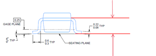
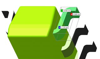
I'm trying to determine the distance between the bottom of the foot (seating plane) and the top of the lead for VPN TLV3501AQDBVRQ1. If TI would specify this dimension on all of your drawings it would save me a lot of work getting parts measured.

-
Ask a related question
What is a related question?A related question is a question created from another question. When the related question is created, it will be automatically linked to the original question.