This thread has been locked.
If you have a related question, please click the "Ask a related question" button in the top right corner. The newly created question will be automatically linked to this question.
Hii
this is mohan
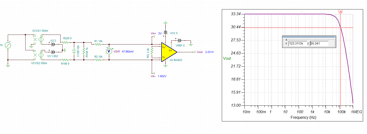
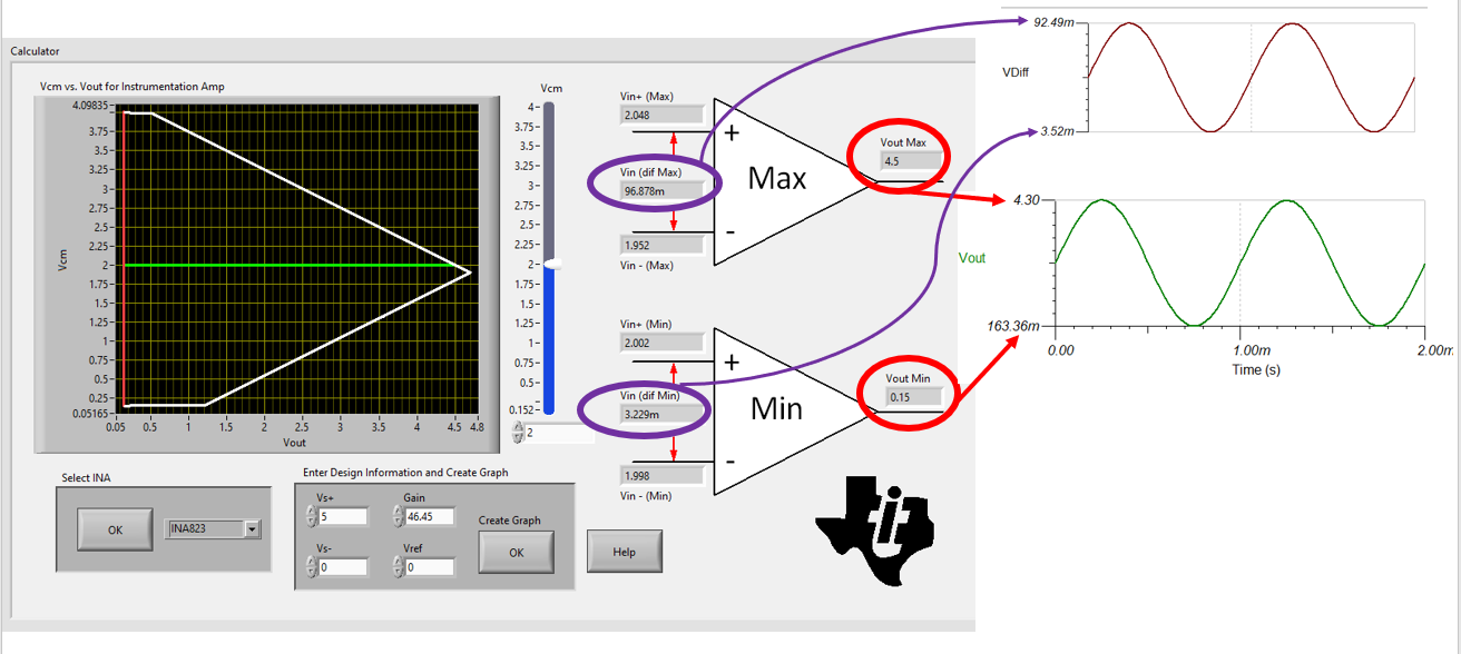
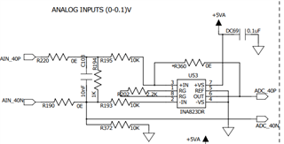
recently we have procured the part INA823 for amplifing the 0.1V to 5V
we are unable to amplify it with supply voltage of 5V and it bee done with supply voltage of 10V
but supply voltage range is 2.7-36V
and i had attached our circuit drawing
can you reply as soon as possible
Regards
Mohan
Hi Mohan,
I have simulated the circuit to understand the parameters in parallel with out Engineers Calculator. I have also adjusted some of the parameters such as the common mode and differential voltages in order to remain within the linear operating range of the device. R360 was also removed.
The DC common mode voltage is set to (2 + 1.952)/2 = 1.976V. The differential voltage is 47.992 mV as shown below and the output is at 2.231 V. The gain of the circuit is 30.34 dB or 10^(33.34/20) = 46.45 V/V. The -3 dB point I see is at 123.3 kHz.
Using the calculator and the Tina simulation I setup the input differential signal such that it stays within the min and max values, and the output also stays within the min and max values.
I am able to gain up the signal in this configuration.
Here is the Tina simulation and links to our free tools to help aid in our discussion.
https://www.ti.com/tool/TINA-TI
https://www.ti.com/tool/ANALOG-ENGINEER-CALC
Are you able to replicate the results from the simulation above?
What are the DC levels that are applied to both inputs?
What is the max peak to peak signal being applied to the input?
I hope this information is helpful in the debug process.
Best Regards,
Chris Featherstone