Other Parts Discussed in Thread: AMC1411
I am using the AMC1411-Q1 for a HV battery sensing application. The output of the AMC1411 is fed to an ADC as well as an analog comparator circuit for detecting over voltage conditions.
I noticed when measuring the output of the AMC1411 with a differential probe that the signal had oscillation at the frequency of 270-290kHz.
I do not see 290kHz oscillation on the input signal to the AMC1411. Nor do I see oscillation of 290kHz on the VDD supply line.
Anyone have any ideas on why the output might look like this?
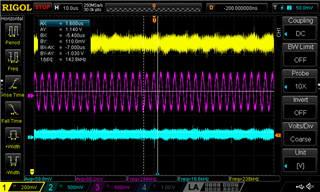
Below is a scope plot I took...
Ch 1 is a 5V line from a benchtop power supply being fed to VDD1 and VDD2
Ch2 is the the IN pin of the AMC1411, (30VDC being fed through a resistor divider)
Ch3 is the OUTP/OUTN being measured with a differential probe.
Noe: In this scope plot, the output of the AMC1411 is DISCONNECTED from the ADC or comparator circuit in my design (in hopes of isolating variables)

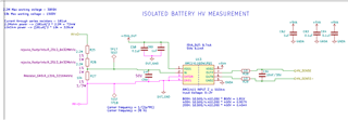
Schematic of this sub-circuit (basically copied from the app note)

Appreciate any feedback!


