This thread has been locked.

If you have a related question, please click the "Ask a related question" button in the top right corner. The newly created question will be automatically linked to this question.

OPA320: Understand a circuit

Part Number: OPA320

Hello,

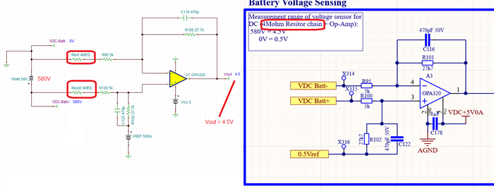
I have a circuit with the OPA320 used but I am not able to understand how they have converted the 580V to 4.5V and how is the opamp working in this case. Please find the circuit in the image below:
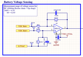

Thanks,
Neha

  • Hi Neha,

    The schematic shows a difference amplifier with a gain of 27kΩ/5kΩ, or a of 5.54V/V.  The transfer function is:

    Vout = G*(VDC Batt+ - VDC Batt-) + Vref = 5.54*(VDC Batt+ - VDC Batt-) + 0.5V

    However, the text description reads "4MOhm resistor chain + op-amp".  If an additional 4MΩ series resistance is present at both VDC BAtt+ an VDC Batt - connections, the gain would be G= 27.7kΩ/(5kΩ +4MΩ) = 0.00692V:

    Vout = 0.00692*(VDC Batt+ - VDC Batt-) + 0.5V

    Therefore, 

    - if (VDC Batt+ - VDC Batt-) = 580V, Vout = ~4.51V.

    - if (VDC Batt+ - VDC Batt-) = 0V, Vout = ~0.5V.

    See below:

    Thank you and Regards,

    Luis

  • Hi Luis,

    Thank you for your response. 
    Also why do we add the 0.5 Refernce?

    Regards,

    Neha Agarwal

  • HI Neha,

    Below is a link for an application note that discusses the difference amplifier, and provides the derivation of the transfer function:

    Difference amplifier (subtractor) circuit

    Essentially, you can use superposition theorem to derive the output transfer function of the multiple input voltage sources in the circuit.

    Using superposition theorem, by inspection, the output transfer function for the difference amplifier is:

    If you let, R1 = R2 and R3 = R4 the transfer function for this circuit simplifies to the following equation:

    Where  the Gain, G is R3/R1, and Vref is added into the output voltage.

    Thank you and Kind Regards,

    Luis