This thread has been locked.

If you have a related question, please click the "Ask a related question" button in the top right corner. The newly created question will be automatically linked to this question.

OPA202: Designing with OPA202

Part Number: OPA202
Other Parts Discussed in Thread: TPS22810, TMUX6219

Hello Team,
We are planning to use the opamp OPA202 in one of our designs.
The Opamp is used as a buffer.
A 0-10V from an analog signal source will be scaled down to 0-5V (The input voltage range of the internal ADC of the MCU).
However, these analog pins of the MCU where the output of the opamp is connected have some other features like the booting configuration of the MCU (Need only at the time of firmware booting).
So a 10K default pull-down is provided at these pins.
During booting, the power to the opamp will be disconnected using a load switch like TPS22810.
The power will be available at the VCC pin of the OPAMP only after booting is completed.
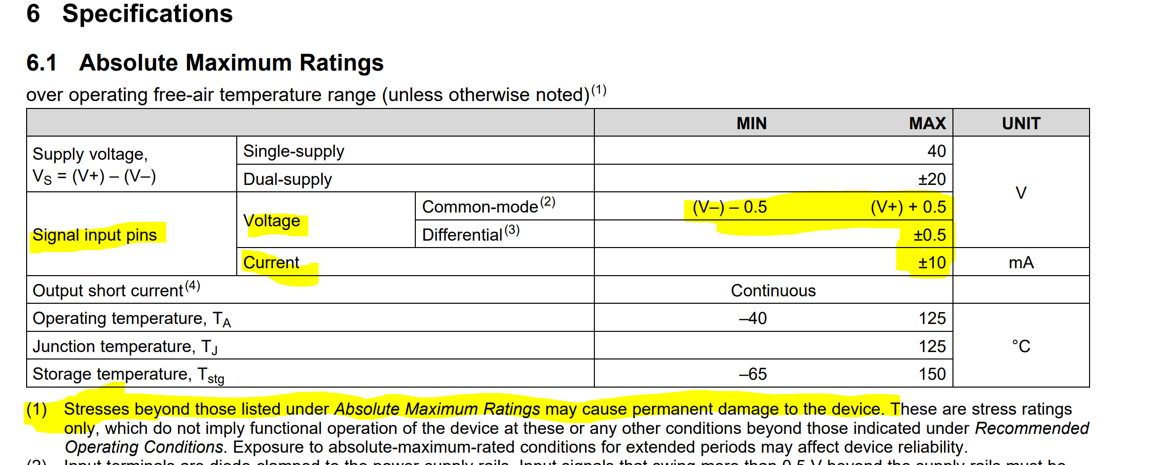
1). Are there any issues when an OPAMP has an input signal at its input pins and is not powered?
2). What will be the output of the OPAMP if no voltage is applied at the VCC pin and a voltage at the input of the OPAMP?
We need a default pull-down in specific pins of the MCU during booting to set the booting configurations (these pins are connected to the output of the OPAMP too to measure the input voltage).


  • Hey Vijay, 

    Since the Op Amp will not be powered on the voltage seen on the output pin will be pulled up or down to whatever level the pull-up resistor is tied to. Pulling the output above or below the supply rail of zero volts can overvoltage the output stage and damage the device. On the input stage I have highlighted the Abs max table below. If the abs max values are violated such as input voltage or current exceeding the supply permanent damage may occur and device degradation can occur over time. For these reasons we recommend not applying the input signal during power down. 

    Best regards, 

    Chris Featherstone

  • Hello Chris,
    Thank you for your reply.
    The output of the OPAMP will be pulled up or down to 5V rail only while the VCC of the OPAMP is 15V (initially no voltage T the VCC pin of the OPAMP.)
    Will the output of the opamp sink the pullup or pulldown voltages?
    The input to the opamp will be 0-10V.
    If we cannot have a voltage at the i put of an opamp when the opamp is not powered, can you give us a better solution? (Will using an analog mux will be helpful?)
    Is it a good choice to use Opamp with a shutdown feature whose output goes to a high impedance state at shutdown?

  • Hey Vijay, 

    If the power supply is +/-15V and the output were to get pulled to either +/- 5V than the output isn't reaching a potential beyond the supply and therefore within the specified operating range of the device. If the output goes positive on a load resistor referenced to ground the device will source current, and if the output goes negative the output will sink current. If the output load resistor is connected to either +/- 5V the output will sink current if the output is below 5 volts and will source current if the output is more positive than -5 V. I give an example below. 

    I have put together an example of a possible solution to the input problem using an analog switch such as the TMUX6219. I have it switching between ground and the input signal. I have attached the Tina Ti file below as well. We offer Tina Ti for free here:

    https://www.ti.com/tool/TINA-TI

    Any switching events require the consideration of over voltage protection (OVP). We have a series on OVP that can be found here and also provides a section for selecting components. 

    https://www.ti.com/video/series/precision-labs/ti-precision-labs-op-amps.html

    There is an application note available below discussing considerations using amplifiers with shutdown modes. 

    https://www.ti.com/lit/an/sboa367b/sboa367b.pdf?ts=1693516107814&ref_url=https%253A%252F%252Fwww.google.com%252F#:~:text=When%20the%20amplifier%20is%20in,one%20SHDN%20pin%20per%20amplifier.

    OPA202 wirth switch.TSC

    I hope this information is helpful. 

    Best Regards, 

    Chris Featherstone

  • Hello Chris,
    Thank you for your reply.


    From the datasheet, it says the input signal voltage level should be within the range of (V–) – 0.5 (V+) + 0.5 (i.e. between -0.5V and 15.5V in our case).
    however, there will be a situation (during the booting of the processor) where the input signals are present at the opamp and no voltage (supply voltage) is present at the VCC of the opamp.
    1). Will this raise any issues?
    2). What will be the output of the opamp at this condition?
    3). We initially need to pull up or pull down some pins of the processor for proper booting. The output of the opamp will be connected to these pins. When booting is completed, we will allow the load switch to deliver power to the VCC pin of the OPAMP.  (The input signal at the input of the opamp can be present at these times). If the opamp source or sink current, it will affect the booting of the processor.
    4). Is it a good choice to use Opamp with a shutdown feature whose output goes to a high impedance state at shutdown?
    5). 

  • Hi Vijay, 

    If you are operating on a single supply than a voltage divider can be used from the supply to the switch on the input as shown below. During power up the switch would be in the position to provide a dc level of mid supply. The input signal can be switched in on the input. Notice that I reference the input signal to mid supply instead of ground. This level shifts the input signal to mid supply or 7.5 V in this case. In the simulation below this is done with a jumper that I labeled Vmid. 

    OPA202 wirth switch (2).TSC

    Best Regards, 

    Chris Featherstone