Other Parts Discussed in Thread: LM2903B, LM339, TLV1811
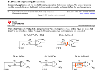
Why the red circled part are 10M and the other resistors are 10k, if we change the 10M to 10k, what will happen and why?

This thread has been locked.
If you have a related question, please click the "Ask a related question" button in the top right corner. The newly created question will be automatically linked to this question.
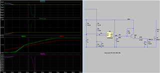
As far as I can see, N+ and N− have the same voltage at that time, so the output is random. Consider adding hysteresis.
I'd guess that the 46.6 kΩ resistor does not allow enough base current for Q1.
Hello Guozhu,
The idea is to place a small differential voltage across the inputs to keep the output in a known state.
There is about 25nA of bias current flowing out of the input and towards ground on the LM339 type bipolar device. See section 2 of the appnote.
The 10MEG resistor is used to generate a voltage drop from that bias current. 10Meg * 25nA = 250mV across the resistor. That places the 250mV on the negative input, which keeps the output low.
If you want the output high, swap the resistors.
hello,Clemens Ladisch,Thanks for your reply. I increased the R8 from 10k to 100k, and found when R8 is above 20k, Ib no pulse current to cause Ic pulse current, and that pulse current will charge the M1 gs. It seems LM2903B output has a leakage curent during the startup if R8 is too low? While the N+ always higher than N- at that time.

For invalid supply or input voltages, the model might not be realistic.
If you want a defined behaviour during power up, use a comparator with POR, e.g., TLV1811.
Thanks Clemens.
Guozhu, for more information on POR, please see [FAQ] How Power on Reset Comparators Simplify Designs - Amplifiers forum - Amplifiers - TI E2E support forums