This thread has been locked.

If you have a related question, please click the "Ask a related question" button in the top right corner. The newly created question will be automatically linked to this question.

LM358: Replacement issue by using TI LM358

Part Number: LM358

Hi Sir,

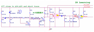
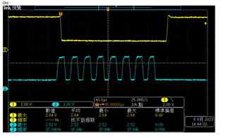
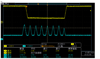
 My customer want to use TI's LM358 to replace competitor's product in thir old design. There're different result by using TI and competitor's LM358 on board. CH1 is pin1 in LM358 and Ch2 is pin7.
Competitor's waveform
TI LM358's waveform
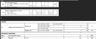
We see there's spec. issue between TI's and competitor's. Is BW the reason for the different test result? Or any other spec./ design we have to take care for the circuit? Thanks for your kindly help.
Regards,

Gary Teng

  • Hey Gary,

    It seems to be the slew rate from the oscilloscope captures provided. However, I have some questions to confirm.

    • Could you provide the voltages on the input of the device?
    • What is the supply voltage? .
    • Using a 10k pull-up on the output of the device is not necessary, and may hurt the performance, what is the performance without the 10k pull-up resistor.

    The LM358B has a better slew rate than the LM358.

    Best,
    Jerry