This thread has been locked.

If you have a related question, please click the "Ask a related question" button in the top right corner. The newly created question will be automatically linked to this question.

problem with Linearity XTR116

Other Parts Discussed in Thread: XTR116, XTR101, XTR115

Hello
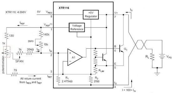
I have a problem with linearity chip XTR116, my circuit is connected according to FIGURE 1. Nonlinearity chip is 0.003%, potentiometer have nonlinearity under 0.1%. I need all nonlinearity under 0.1%, but when I measure this circuit, nonlinearity is bethween 0.3 to 0.4%. You know,  what could be a problem ?  

Thanks for help
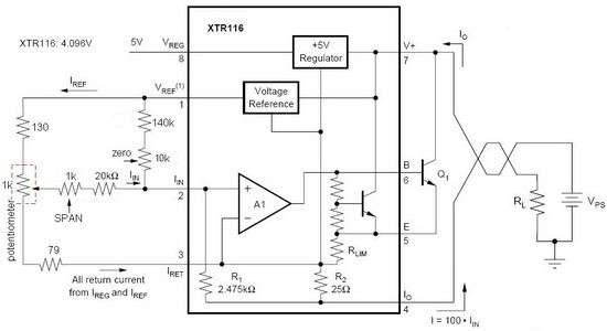
 

                                                        Figure .1
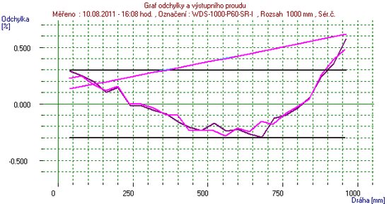
                                                                        Figure.2

  • Hello Martin,

    Thank you for the schematic and the information about your circuit.  First thoughts would be to verify that the span and offset potentiometers are not drifting over time/temperature/voltage and causing some of the errors you're seeing. 

    We will need a little more information to help debug further.  What is the application for this circuit and what is controlling the potentiometer?  When doing the error analysis calculations, is the potentiometer's resistance verified with a calibrated source?  Or is the sensor swept from zero-scale to full-scale and the output's linearity is compared strictly to the sensor input?  

    What is the X axis in the graph?  I did a google translate from Czech to English and received "track" as the translation for the X-axis and "Deviation" for the y-axis.  Is this some type of linear actuator?  What do the three plots represent on the graph?  There are two that look similar and a third very linear plot.

    What temperature are you operating at?  What is the supply voltage and it's variation during testing (if any)? 

    Looking forward to your reply.

    Regards,
    Collin Wells
    Precision Analog

  • Hello Martin,

    Please confirm whether the Span and Zero potentiometer wipers are connected or not.

    As shown in your schematic, they appear to be floating.

    Regards,

    JayantD

  • Chip XTR116 I will use als 2-wire current electronic for Draw-wire displacement sensors. I tried chip XTR101, this solution was very good, but I search chiper solution and I select XTR116. Draw-wire displacement sensor have measuring range 1m, this is axis X in graph

    (distance in mm) and Y axis  is Deviation from linearity.  In graph are tree plots represent course deviation from linearity measured distance from 0 to 1m  (first plot) and from 1 to 0 m (second plot). Last plot (very linear) is course of current.

     Potentiometer is linear and for range 0 to 1m of sensor  is from zero-scale to full-scale. The potentiometer's resistance is verified and have linearity under 0,1%.

    Power supply voltage for electronic is 24V and variation during testing is not.

  • Hello Jayant,

      Yes, ok. In my schematic was potentiometer only indicated. Potentiometer wipers are connected. In figure 3 is modified schematic with really connected potentiometer.

      Regards

                Martin

                                                          Figure 3

  • Thanks, Martin.

    I recon that by now you must have established the linearity of the XTR116 by feeding millivolts from a known source and plotting output current. If this is within the tolerence band, the source of error seems external to the circuit.

    Let us wait and see what Collin has to say about this.

    Regards,

    Jayant

  • All,

    I may be able to provide some insight on this issue:

    Potentiometers are specified for linearity by measuring their ratiometric linearity as a voltage divider. Used in this way, the contact resistance of the wiper does not affect linearity. In the circuits shown in the previous posts, contact resistance affects linearity and accuracy.

    To use a potentiometer in ratiometric mode, consider the circuit below. Here, the wiper resistance does not significantly affect the because the wiper is not loaded. I've shown resistor values for the XTR115 but values could be easily adjust for the XTR116.

    Regards, Bruce.

  • Hi Jayant,

    Thank you for your comments.  I'm glad to see you're helping others with their XTR designs!

    The XTR devices are tested for nonlinearity in a similar manner as you've described during their production to ensure that the max nonlinearity does not exceed 0.01% for the XTR116U devices and 0.02% for the XTR116UA devices.  So the error is somehow due to the external circuitry.  I am not as familiar with these types of sensors as my colleague Bruce, so I think he's likely found the culprit of the non-linearity.  Buffer the signal with a low-offset, low-drive op-amp and re-do your experiment to see if the non-linearity is reduced within specifications.

    Regards,
    Collin Wells


  • Dear All,

    Bruce has given valuable inputs and it will be interesting to know about the results. But I think Martin is concerned about the nonlinearity of the measured length of the drawn wire, and not the voltage to current conversion part, since it is perfectly linear on his attached graph.

    Martin, Will you please describe how the readings are taken for plotting ?

    Best Regards,

    Jayant

  • Hello Jayant,

     I have the output precise resistor 250ohm connected and I measure voltage across the resistor with Keithley. For plots in graph  I converted back to current.

      Best Regards,

                   Martin

  • Hello Martin,

    If I understand correctly, you are measuring a known length of drawn wire in mm. For this known length you are measuring the voltage across the 250 ohm precise potentiometer. This is the input signal to the XTR116. What are the measured values of the current output from XTR116 at these input values?

    The rest of the part, "For plots in graph  I converted back to current." is not clear to me. Will you please explain in detail ? This is required to establish whether the nonlinearity is originating within the XTR116, or is external to it. Can you please do this exercise of plotting the input and output of the XTR116 and inform the results ?

    Regards,

    Jayant


  • Dear All,

     thanks for your suggestions and discussion. You were right. Problem was in external components. I joined OPA33 to XTR116 and I performed additional tests. Below are graphs and my results.

    Graph 1- XTR116 without OPA33   - bad linearity (greater than 0.2%)


    Graph 2- XTR116 with OPA33    - linearity better (less than 0.2%)

    Now, I measured only poti, linearity very good, less than 0,1%.  I then measured the potentiometer with other external components (input XTR116)  - graph 4

        Graph 3- only potentiometer 1k

    Graph 4- potentiometer 1k with external components (rezistors and trimmers)

    There was bad linearity - (0,5%) - problem is in input circuit from external components. I change schematics input circuit (I added 1k rezistor in parallel with potentiometer) and now is linearity less than 0,1%


  • Hello Martin,

    Great news!  I am glad that your system is producing results that you are satisfied with.  Thank you for the additional information it will definitely help other people in the community!

    Best Regards,
    Collin Wells
    Precision Analog