Other Parts Discussed in Thread: ADS8862,
Dear Technical Support Team,
I have Output Oscillation issue with 2700pF on output.
The configuration is buffer for ADS8862.
When Riso is inserted on output, then output seems to be stable(No oscillation).
See attached file.
Q1
Could you provide two TINA TI simulation?
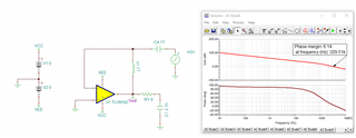
① Phase margin and stability when driving TLV9102 with CL=2700pF and Riso=0Ω
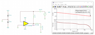
② Phase margin and stability when additionally inserting Riso=2.2kΩ with CL=2700pF
Q2
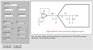
If you have more appropriate RC value for ADC driver, please could you share them?
P.S
ADS8862 datasheet shows Charge-Kickback Filter and RFLT ≦22Ω and CFLT ≧590 pF(Figure 62. Charge-Kickback Filter), but my configuration is simply RC filter for ADC driver.
Best Regards,
ttd