This thread has been locked.

If you have a related question, please click the "Ask a related question" button in the top right corner. The newly created question will be automatically linked to this question.

XTR117: XTR117 and INA321E

Part Number: XTR117

Hello Team,

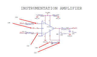
I have resolved the heating issues now i have voltage difference in-between the INA321e and the XTR117 transmitter.

Due to the Voltage difference the output current is only 0.200mA 

  • Yuvakumar,

    1. The XTR117 is designed as a current gain amplifier (Iout = Iin x Current_Gain).  Thus, it is expected that you will get a voltage drop across resistor R8.  The current gain for this device is 100A/A, so the input current would need to be 20mA/100 = 0.2mA for a full scale 20mA output.
    2. The selection of components for a similar XTR is covered in https://www.ti.com/lit/an/sboa107b/sboa107b.pdf.  Please double check your component selection.  
    3. The same document from above has a section on grounding considerations for 2-wire XTR devices.  The key important point is that you need to make sure that the loop supply is floating.  In your design I see a zero ohm resistor between GND and ISOGND.  I'm not sure if this is populated.  If it is populated it could be a potential issue.  Read through the "Grounding considerations" section an double check your grounding.
    4. Another potential issue with this kind of application is your total circuit power.  The 2-wire XTR devices provide all the power for the subsystem from the loop power.  Thus, to get the 4mA to 20mA range all the current of each device in your system must add up to less than 4mA.  I don't think this is the problem in your case because violating this condition will normally lead to higher output currents (in your case the output current is 0.2mA).
    5. It would be really helpful to show voltage measurements on all the key points (e.g. power supplies, inputs, outputs).  Also, if you can include the full schematic (pdf) that would be helpful (maybe something not shown is an issue). 
    6. I suspect the issue may be related to the LDO and the grounding issue I mentioned earlier.  The LDO and sensor seem to be powered by a 24V supply.  These 2-wire XTR systems are supposed to be loop powered.  Do you have more than one XTR connected to the same ground?  How is the 24V supply grounded?  

    Best regards,  Art

  • Hello Art Kay,

    I have attached the voltage measurements of the INA321E.

    please have a look, the above attached image is the full schematic.

    I have changed the XTR and still i can observe the same issue.

  • Yuvakumar,

    1. Common mode range violation is a very common issue with instrumentation amplifiers.  Your measurements help me to confirm that the common mode range looks good in your application.  The way to check common mode range is to use the Analog-Engineers-Calculator tool.  See screen shot below showing a linear output range of 0.025V to 3.8V for your case.
    2. I should have asked this before:  Is the INA working as you expect it should?  Your main concern in the original question seemed to be related to the XTR117 operation.  If you think the INA is working correctly, we can focus on the XTR.
    3. Regarding my last post:  My main concern relates to the grounding of the XTR117.  Is the grounding floating relative to the loop power supply?  Also, is the Iret GND (GND_ISO) connected to anything not shown in the schematic excerpts given in your original post?  Most problems related to the XTR117 relate to the grounding.  I think your 24V supply is likely the issue.  All power in this kind of circuit should be provided by the loop supply.
    4. Perhaps one other thing to check.  It is always a good idea to check key input and output nodes with an oscilloscope as well as with a DMM.  The main idea is to look for instability, noise, or oscillations.  I don't really expect this is the problem, but it's a good thing to check for completeness.
    5. I really think item 3 above is the issue.

    Best regards, Art