This thread has been locked.

If you have a related question, please click the "Ask a related question" button in the top right corner. The newly created question will be automatically linked to this question.

INA253EVM: INA253EVM

Part Number: INA253EVM
Other Parts Discussed in Thread: INA253,

Dears,

I'm now targeting to use INA253 as the way of each current measurent for Power supply, GND, Outout of Audio Class-D amplifer.

After purchaisng INA253 EVM, I connected three of them to each section to measure each current wihtout any modification of INA253EVM as below  

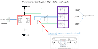
Inserted Vs by 5V. So Ref2 voltage has been connected to 5V and Ref1 is GND.. When each pin of "OUT" is measured, it's around Power(2.325V), GND(2.307V), Output of Amplifier(2.3V).

Could you help to advise on whether it's a right voltage or not? if not, could you help to give any way to measure it? if yes, could you help to inform on how to convert /caluraqte it as a curent flow?

Help to get any supporting 

Thanks

Best regards,

Jaydon

  • Hey Jaydon,

    Welcome to the forum. Thanks for posting.

    1. Would you please confirm where you are probing ground for these measurements?

    2. Would you please measure the VS pin voltage?

    3. Is the OUT pin driving or connected to any external circuitry?

    The output should be biased to the mid point between VS and GND. 2.3V is outside specified range.

    Sincerely,

    Peter

  • Hi Peter,

    Thanks for your kindly feedback and here below is my feedback on our questions

    1. Would you please confirm where you are probing ground for these measurements?

        --> I'm connection the GND of probing it  into each board GND together.. and three GNDs of the INA253 EVM have been connected together 

    2. Would you please measure the VS pin voltage?

        --> 5V connected 

    3. 3. Is the OUT pin driving or connected to any external circuitry?

       --> No.. it's just connected to oscilloscope and measured the otuput voltage 


    Help to get your advice on any checking potins again.. By the way, could you help to also advise on how to calurate the current once there will be the voltae level of "the OUT pin"?

    Should I calurate it with 100mV/A? for example, if the voltage of "the OUT pin" is 2.6V, shoud it be calcurated  by 0.1V : 1A = 2.6V : X ?

    Help to get your feedback

    Thanks

    Best regards,

    Jaydon 

  • Hey Jaydon,

    Can you please get an accurate voltmeter and measure the VS pin of the INA253EVM with respect to INA253 GND pin and also the ground of you syste (TFA low-side FET ground)? It is imperative that we know that this voltage rail is not getting loaded down from 5V to 4.6V.

    Also, the ground of each INA253EVM panel (so A1, A2, and A3) should each have its own dedicated cable to your system (TFA) ground. Essentially, the ground of any and every IC, must all return back to a single point (star connection), not all connected in series.

    I think you should simplify your test setup and only connect one INA253EVM panel to your 5V supply and ground. So float the other two panels entirely. You could keep the internal shunt (IS+ and IS-) lugs still connected in series, but this is all. Maybe also try removing these connections as well if it is easy enough.

    When one REF pin is connected to Vs and the other is connected to GND, Vout for the INA253 is calculated as:

    Vout = GAIN*load + (Vs-GND)/2, where gain in mV/A.

    Sincerely,

    Peter

  • Hey Jaydon,

    I am going to mark this thread as closed, but if you have any updates, concerns or questions please post back here or start a new thread.

    Sincerely,

    Peter