This thread has been locked.

If you have a related question, please click the "Ask a related question" button in the top right corner. The newly created question will be automatically linked to this question.

TLV9064: Input impedance without supply

Part Number: TLV9064
Other Parts Discussed in Thread: TLV2262, TLV9062, OPA2310, OPA2323

Hello,

I am designing a circuit to measure the voltage of a glass electrode sensor which has a very high output impedance (>100Meg). Most opamps have an even higher input impedance (>10G) so this isn't a problem at first sight. Given some other design constraints I went for the TLV9064 which worked great in my initial testing.

However when I cut power to the circuit, the input impedance of this specific opamp drops significantly, which puts a lot of load/wear on the glass electrode sensor, especially its electrolyte, which will greatly reduce its lifespan. When given power again to the circuit the sensor takes a long time to recover as well (tens of minutes). This isn't the case for all opamps, but this unusual spec is rarely mentioned in any datasheets. For example I have another design around the MCP6022 which maintains its input impedance even when not powered.

My quesiton: What other opamp can I pick instead of the TLV9064 which is also available in VSSOP package and doesn't have this issue ? This could avoid any pcb changes...

Here are some additional thoughts for anyone interested in this issue:

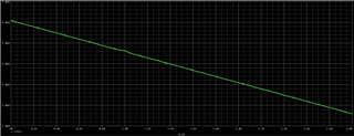
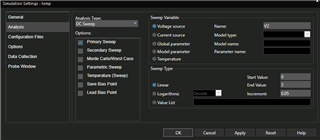
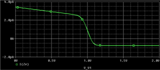
I tried to replicate this in simulation by performing a DC sweep on the supply voltage. These are the results :

Simulation schematic

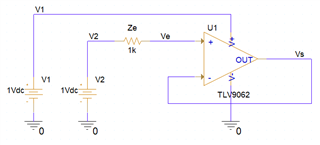
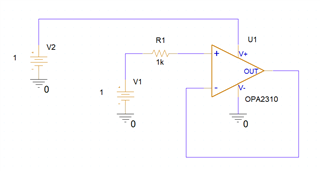
Simulation Schematic (tested with Ze 1k and 100Meg)

TLV9062 input current vs. VCC sweep

TLV9064 input current (V+) vs. VCC sweep - Ze=1k

I didn't have the spice model for the MCP6022, but I found the TLV2262 (not available in VSSOP sadly) which doesn't seem to suffer from this issue (although this might also be the simulation model just not being accurate in this edge case ?).

For such old parts the equivalent schematic is provided in the datasheet, but for the newer TLV9064  this is sadly not the case. This makes it hard to understand the input stage architecture and identify what specific input stage type might fit my requirements.

TLV2262 input current vs. VCC sweep

TLV2262 input current (V+) vs. VCC sweep - Ze=1k

Regards,

  • Hi Lorenzo,

    Does the glass electrode sensor retain it's voltage charge after the supplies to the op amp is off?

    Best Regards,

    Robert Clifton

  • Hello Lorenzo,

    You need an op amp with "fail-safe" inputs. No diode from IN to positive supply rail ; here are two options. 

    OPA4310IPWR

    OPA4323IPWR

  • Hi M. Clifton,

    Yes and this is part of the problem. The sensor outputs a voltage, but isn't powered. Therefore this voltage is always present on the input, even when the opamp isn't powered. This voltge is extremely "weak" though (very high impedance) to basially no current can be drawn from the sensor.

    Even though when the circuit is turned back on the sensor slowly comes back to its initial voltage, the increased "load" on the sensor causes damage and will reduce its lifespan.

    Regards,

  • Hi,

    Thank you for these suggestions, I will look into them.

    It indeed makes sense that current can flow through this upper diode when it becomes direct biased as VCC falls below its voltage.

    Sadly, as I stated in my original post, a lot of manufacturers don't give the equivelant input schematic and architecture for modern components so it's not always possible to know if these upper diodes are there or not.

    Regards,

  • Hi Lorenzo,

    Usually you can tell by looking at the input pins voltage range. I recommend taking a look at the Op Amp ESD Protection Structures to get a better understanding of this. Essentially if the inputs are able to go above the supply voltage range by 0.5V to 0.7V then you can basically guarantee that there's diodes to the supply rails. 

    Best Regards, 

    Robert Clifton

  • Thanks for the fast reply!

    Working with such high impedance circuits can make things difficult while debugging as you can't just probe with a common 1Meg oscilloscope.

    I will take a look at the document you suggested, because I have to admit I'm surprised they manage to put ESD diodes and still maintain a high input impedance. Regular PN junctions will have way too much reverse leackage, so they must use diode connected FETs or something ?

    Anyway the information provided by both of you is already plenty to continue my investigation, many thanks again.

  • Hi Lorenzo,

    In CMOS architecture, the ESD diodes are the dominant source of the input bias current. However this is still usually in the picoamperes. That's usually the biggest effect of the diodes under normal operation since they won't be conducting. 

    As far as the exact architecture of diode they use, I'm not sure. But the design has been proven to be very robust as they are industry standard. 

    Best Regards, 

    Robert Clifton 

  • Hi Lorenzo,

    I'd like to add that OPA2323 would likely be a better option for your application since the OPA2310 has lower bandwidth than the TLV9062. The VSSOP package isn't out yet but will be coming very soon. 

    Best Regards,

    Robert Clifton 

  • I looked into the two opamps you suggested and wanted to test them with the same simulation I showed in my initial post, and I am having trouble with the OPAx310.

    In the datasheet the input bias current is specified at only 30pA but in my simulation I get over 500µA. Note that I used the exact same simulation schematic sheet as before, only changing the opamp.

    This is certainly an issue with the simulation (either the model itself or my simulation). Given that I still would like to find a result close to the datasheet do you have some idea as where this might come from?

    OPA2310 Input Bias Parametric Simulation

    OPA2310 Simulation Schematic

    Simultion configuration

  • Hi Lorenzo,

    I'm not sure what happened in your simulation but in mine I got this: 

    Maybe change the value to just 1 rather than 1Vdc? 

    Best Regards,

    Robert Clifton

  • I tried creating a new project in Cadence, using the example project from the library and even run the same simulation on LTspice without success. Maybe there is an issue with the model I use after all. The model is the one I directly downloaded from TI here : https://www.ti.com/lit/zip/sbomc62

    Sorry to bother you with this issue. Do I need to create a seperate topic ?

    LTspice simulation

    OPA2310.lib

  • Hey Lorenzo,

    I'll answer while Robert is OOO. Could you please do me a favor and run a DC bias simulation with the op amp with a valid supply voltage? Then could you tell me what the supply current and input bias current is?

    There may have been an error in the upload process, and it appears that the pinout of the device is incorrectly mapped.

    We will work to get this resolved as soon as possible.

    Best,
    Jerry

  • Here is the bias point simulation. Even with the propper supply voltage something is clearly amiss because the output voltage is not equal to the input voltage inspite of the unity feedback.

    Bias simulation

    Regards,

    Lorenzo.

  • Lorenzo,

    Is op amp V+ current still 18.47pA even if V2 was 0V?

    Is V+ pin connected? The model doesn't like something as none of the signals look correct.

  • Hi Lorenzo,

    We have discovered that the model pinout is wrong. We are working to correct this but in the mean time here's the pinout:

    • Real VCC is on IN- pin
    • Real VEE is on OUT pin
    • Real OUT is on IN+ pin
    • Real IN+ is on VCC
    • Real IN- is on VEE

    This incorrect pinout is exclusive to the OPA2310 model. I believe the reason mine worked was I was using an older version. Very sorry about the confusion that this has caused. 

    Best Regards,

    Robert Clifton

  • Hi M. Clifton,

    This was indeed the issue, and now my simulation is working as expected.

    Thank you for your help,

    Regards,

    Lorenzo.

  • Hi Lorenzo,

    I'm glad this was able to solve the issue you were seeing.

    Best Regards, 

    Robert Clifton