This thread has been locked.

If you have a related question, please click the "Ask a related question" button in the top right corner. The newly created question will be automatically linked to this question.

INA240-Q1: Current Sense from Supply Source

Part Number: INA240-Q1
Other Parts Discussed in Thread: INA240

Hi Team,

My Software Team is Facing issue in Reading ADC Results in Software , 

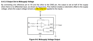
Programming is Implemented as per Datasheet Guideline .,

But its Showing Wrongs Vales ., ( We are in Mass Production Phase & We are getting this Issues )

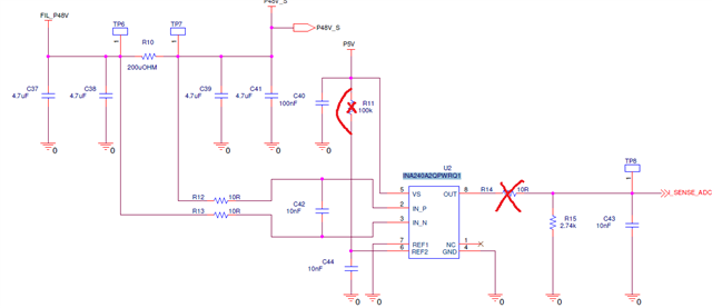
Please Let me Know and Changes needed to done in Hardware or

Any Formulas based on Schematics which i can Update in my Software .,

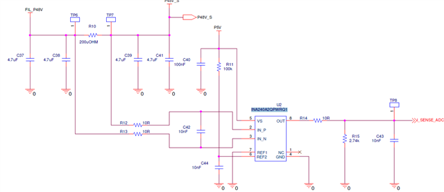
Please Find Attached Schematics 

  • The INA240-Q1 has an analog output, so I do not understand why any programming is involved.

    What is the purpose of R11? The REF inputs should be connected to low-impedance voltages; just short R11 (and then you don't need C44).

  • Hi Pavan,

    Please consider the inputs from Clemens. R11 needs to be removed, otherwise you’ll see large output error.

    Also R14 might be too small, consider increase it to 150 or so. R15 can be either removed or increased substantially to reduce systematic error.

    Regards, Guang  

  • After removing the R11,R14 & C44

    we tried to vary the input voltage by varying the load the below observations are noted (which are not matching the output mentioned as per data sheet) 

    V R (Ohms) I Sens O/P (mV)
    48 No load 0 1780
    48 16 3 1751
    32 8 4 1735
    40 8 5 1720
    48 8 6 1708

    As per the data sheet our configuration is as below from the section 8.4.3.2 Output Set to Midsupply Voltage

    But the observations at the output are not aligning the Vref. I expect when there is no load or no current Vout = Vref/2 (2.5V).

    could you please let us know why the behaviour is like the output voltage is reducing with increasing in current?

  • Hi Pavan,

    Output voltage changes inversely typically means the input seen by INA240 is connected such that it is negative in polarity.

    R11 should be removed but replaced by a short; C43 needs to be removed or reduced to 1nF or smaller. I would focus on getting the zero-current output to be 2.5V.

    Regards, Guang  

  • Hello Guang,

    Thanks for the reply,

    To not to make mis understanding, a small correction in the previous comment I have removed R15; not R14 (only removed suggested resistors or capacitors), 

    Now, I removed the C43 also and tested, I could see the output voltage is little improved (but with no load :1850mV; with 3A : 1819mV).

    Kindly check about how to get no load output as 2.5V and let me know further updates.

    Best Regards

    Revanth Bayyana

  • Hi Revanth,

    Please configure like below. then measure all 8 pin voltages at the device.

    If you don't get 2.5V at the output while all other pin voltages are as expected, please swap with a new unit/board. The unit could have gone bad.

    Regards, Guang  

  • Hi Zhou.,

    I have Installed TINA For Performing Simulation,

    Can you Share me Library or Library Link for INA240-Q1,

    So., I Could Do Simulation & Cross Check my Schematics & Its Results.

    Regards

    Pavan.

  • Hi Pavan,

    That is a really good idea.

    Please go to the product folder, and download this  ref design. It contains complete circuits already so you don’t have to draw everything from scratch:

    Regards, Guang