This thread has been locked.

If you have a related question, please click the "Ask a related question" button in the top right corner. The newly created question will be automatically linked to this question.

XTR305: Schematic review

Part Number: XTR305
Other Parts Discussed in Thread: TINA-TI

Dear team, 

My customer would like to use XTR305 for their analog output module(voltage and current output) application with below requirements. 

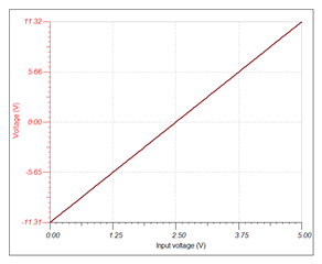
- DAC output 0 ~ 5V, 12bit

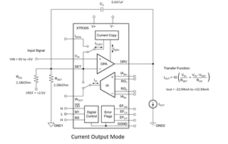
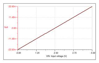
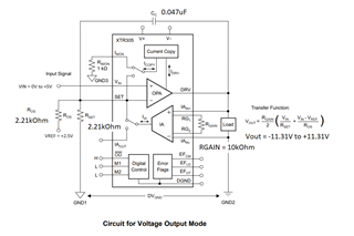
- Input signal : 0V , output -11.35V and -22.7mA

- Input signal : 2.5V , output 0V and 0mA

- Input signal : 5V , output +11.35V and +22.7mA

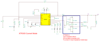
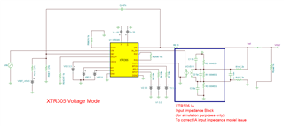
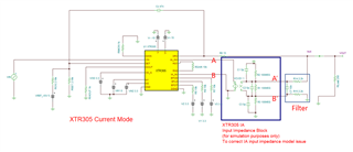
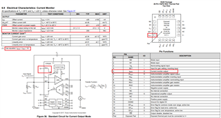
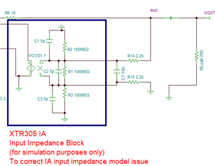
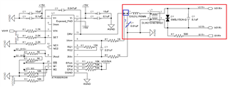
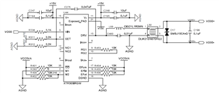
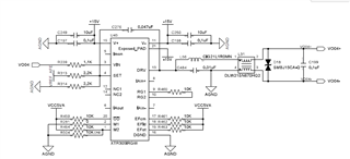
Please review below customer schematic and let me know your opinion. 

or 

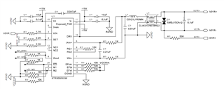
Which schematic is correct? please recommend schematic to meet customer requirement. 

Thank you. 

  • Hi Dino,

    The XTR305 can be configured in either current output mode, or voltage output mode; by controlling the M1, M0 inputs.

    Current Mode:

    To support current mode, set M1=Low, M2 = High. 

    If we set VREF = +5V, RSET = ROS = 2.18kΩ, this will provide an IOUT = -22.94mA to +22.94mA for an input voltage VIN = +0V to +5V:

    See simulation below, provides an IOUT = -22.94mA to +22.94mA for an input voltage VIN = +0V to +5V:


    Voltage Mode:

    To support voltage mode, set M1=Low, M2 = Low. 

    If we set VREF = +5V, RSET = ROS = 2.21kΩ, RGAIN = 10kΩ this will provide an VOUT = -11.31V to +11.31V for an input voltage VIN = +0V to +5V:

    See simulation below, provides an VOUT = -11.31V to +11.31V for an input voltage VIN = +0V to +5V::

    TINA-TI simulations attached.

    XTR305_voltage_mode_and_current_mode_April-4-2024.zip

    Thank you and Regards,

    Luis 

  • Hello Luis, 

    Thank you for your strong support. 

    I have some questions. 

    1. For current mode,

    - Do we have to add Rgain 10Kohm and filter device(C7, R14,R15)? 

    - In real schematic, Do we have to connect  A - A' and B - B' without Input impedance block?   

    - There is no filter and Rgain at standard circuit for current output mode of the datasheet. Is this for supporting both voltage and current output in your schematic? 

    2. Voltage mode

    - How about voltage mode schematic? This is same question for current  mode. 

    - Do the road resister need in customer circuit? 

    3. In below customer schematic, Can you guess the purpose of L36(Common mode filter)? 

    - I don't think this device can make a differential signal. please let me know your opinion. 

    - If this circuit is in the output, is the voltage/current output of XTR305 operating normally?

    Please review above question and please let me know your opinion. 

    Thank you. 

  • Hi Dino,

    Luis is out of office today. 

    Enclosed is one of the XTR305 application note: Compact Programmable 4-mA to 20-mA and ±10-V Analog Output Reference Design for AC/Servo Drives

    https://www.tij.co.jp/lit/ug/tidue87/tidue87.pdf?ts=1712863863745&ref_url=https%253A%252F%252Fwww.google.com%252F

    1. For current mode,

    The current mode is V-to-I converter. In the Figure 36, the input voltage is 0 to 4V and the output is will respond to the transfer function as shown in the diagram. 

    If you want to convert V-to-I, the V-to-I current conversion is sourced/sinked from the DRV pin or pin 13 of the op amp.  The output current is able to convert from input voltage up to ±24mA linearly. Typically, the output DRV pin13 is used to source current from input voltage in V-to-I conversion. 

    Do we have to add Rgain 10Kohm and filter device(C7, R14,R15)? 

    In current mode, this part of circuit is not needed, since Imon pin is shown the Idrv/10, if the voltage at the Imon pin may be monitor, if it is driving a resistive load, say 1kΩ.

    You may connect the instrumentation amplifier (IA) for other purposes, but the IA input connection is not needed generally.  

    Do we have to add Rgain 10Kohm and filter device(C7, R14,R15)? 

    - In real schematic, Do we have to connect  A - A' and B - B' without Input impedance block? 

    The impedance block is for the simulation only. In real schematic, these are not needed, except the filters (if the filtered input signals is required). The input signals to instrumentation amplifier may be single-ended or differential input, depending on the application. 

    If you provide the input design requirements, I can put a simulation together for the application. 

    2. Voltage mode

    - How about voltage mode schematic? This is same question for current  mode. 

    - Do the road resister need in customer circuit? 

    In voltage mode, the IA input connection is need to be connected, if you want to measure the load current via IAout pin. The Rgain resistor is needed, since IAout's current operating range is within ±2.4mA. Below is the operating specification of the IA.  

    The load resistor indicates the load that Vdrv pin13 is driving. The load may be your driving device or something else. If Vdrv is driving a load, then the application may be interested to measure the load current, where IAout may be used to monitor the load current. 

    The IAout is a function of 2[(Ain+) - (IAin-)]/Rgain, which you have to configure the output Imon  range within ±2.4mA. It is your option to define what the relationship between I_load vs. Imon.

    You would need to place known or fixed shunt resistor to monitor the load current, where the shunt or sensing resistor in series with your load (say Vdrv is driving is a complex load). In this case, you may measure the load current differentially. The simulation is shown a single-end current measurement across the load resistor (one end of the load resistor is connected to GND). 

    3. In below customer schematic, Can you guess the purpose of L36(Common mode filter)? 

    - I don't think this device can make a differential signal. please let me know your opinion. 

    - If this circuit is in the output, is the voltage/current output of XTR305 operating normally?

    What is your driving application? based on the datasheet, L36 is common mode choke with impedance of ~67Ω @100MHz. 

    A common mode choke is used to filter out unwanted high-frequency noise signal from external sources of the system.

    https://www.murata.com/products/productdata/8796758048798/EFLC0010.pdf?1655782218000

    Is this the actual XTR305's output stage?  I need to know more about the driving application, and I may be able to tell you what is the designer is trying to do. I think that XTR305 is operating in voltage mode. 

    The circuit below is missing something, and I do not understand the design intent. XTR305 may be configured as voltage or current driver with limited output current. On the right side of nodes marked in red, it looks like that it is higher voltage application with LC LPF + common mode choke + TVS voltage clamps etc.. If the customer wants to measure the XTR305's driving current, there should be a shunt resistor inside of blue box, and DRV output is unable to drive 0.01uf capacitive load directly. So please let us know what is the application and/or the design intent. 

    If you have other questions, please let me know. 

    Best,

    Raymond