This thread has been locked.

If you have a related question, please click the "Ask a related question" button in the top right corner. The newly created question will be automatically linked to this question.

TLV2254: TLV2254

Part Number: TLV2254

Hey,

I've already design a three stages amplifier by using mic863 and all stages gain as 55.5, 11 and 1 and I'm using +/-2.5V dual power supply for this mic863, when i give 8mVp-p as input by varying frequency from 1KHz to 50KHz i notice that from 5 KHz frequency to 10khz frequency i got maximum output as around 450mV for 1 stages , 4.8V for 2nd stages and 4.8V for last stages . so i think it's bandwidth is between 6khz to 10khz and in this I'm also interested in 5.6khz frequency , but i want to that how i can set this type of bandwidth , 

i think it's set by using a equation bandwidth = GBP/Gain, 350KHz/ 55.5 so my bandwidth is around 6KHz correct? please tell me if it's correct or not and if not than tell me how to calculate.

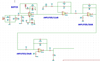
now , i want to design a amplifier using 3 stages of 24, 20 and 11 as i want gain around 5280 to amplify 0.346mV signal up tp 1.5 V , also I'm interested in 32.768KHz frequency so as mention in case 1 i want that my output should come maximum above 30 or 28 khz frequency or it should properly amplify a 0.346mV signal with frequency 32.768khz to 1.5V at output), so i think as per my knowledge with 750KHz GBP i can do this

so please let me know the proper calculation that how to do it , I'm really confused with and also suggest me which op.amp ic will suitable as per my requirement that a signal with 32.768khz with 0.346mV will come around 1.84 or 1.5V with same frequency at last stages. if any further information are required you can ask me 

  • Hi Harsh, 

    i think it's set by using a equation bandwidth = GBP/Gain, 350KHz/ 55.5 so my bandwidth is around 6KHz correct?

    This calculates the cutoff frequency (-3dB) point. In order to calculate the recommended gain bandwidth for the amplifier you need, multiple the gain * input freq * 10. Multiplying by 10 ensures that the design is kept within a specific margin where the closed loop gain is flat. Please see this article here for more information: https://www.ti.com/lit/an/slyt383/slyt383.pdf?ts=1714074908632&ref_url=https%253A%252F%252Fwww.google.com%252F 

    So for your second circuit with 3 stages of 24, 20, 11: GBW = 24 * 32.768kHz * 10 = 7.86MHz. So it's recommended to use an amplifier with a GBW at least 7.86MHz. Recommend trying to use TLV9064 (10MHz GBW). 

    Other factors to consider is going to be noise and offset voltage. Do you have a schematic that you can share so we can see what the input and output stages would look like for each of the stages? 

    Please let me know if you have any questions.
    Thank you!

    Best Regards,
    Ashley

  • Yes , of course I can share you a schematic , in this schematic my first stages is as buffer which's input is around 0.346mV with 32.768KHz and expected output is around 1.8V 

    and please suggest me a better approach or a reference schematic also , a better gain selection, or need to go for a 4 stages please do suggest

  • Hi Harsh, 

    Let me simulate some scenarios and devices to see what can best optimize this. Is the buffer stage necessary for your design? The less number of stages, the better. 

    Regards,
    Ashley

  • okay , please reply as soon as possible

  • Hi Harsh, 

    As mentioned in my last post, could you clarify if the buffer stage is required for your design? And is it required as the first stage? This impacts what devices could be used for the application otherwise we would recommend a different device. 

    Thanks!
    Regards,
    Ashley