This thread has been locked.

If you have a related question, please click the "Ask a related question" button in the top right corner. The newly created question will be automatically linked to this question.

OPA564: OPA564 power supply

Part Number: OPA564

Hi,

I'm using the OPA564 with Vanalog = +/-5,5V.

I read in the datasheet that (V–) + 3.0V ≤ VDIG ≤ (V–) + 5.5V

So I understand that I my Vdig must be comprised between -2.5V and 0V, so it must be negative.

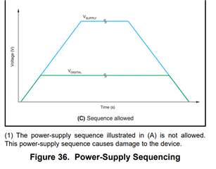
But I can not understand how to realize the power-on sequence described in the fig.36 of the datasheet. Does that mean that I have to start my Vdig sequence from -5V5?

Moreover, does Vdig negative means that all the flags will be negative too?

Thanks,

Sylvain

  • Hi Sylvain,

    You are correct that the VDIG supply must be between 3.3V and 5.5V as referenced to V-. This means for your supply of V- = -5.5V, VDIG can be operated at 0V.

    For your power supply sequencing as shown in figure 36, consider that Vsupply = (V+  V-) and Vdigital = (V- + VDIG) where VDIG is the voltage at the digital supply pin (pin 7 or 14 depending on package).

    Consider sequence C in figure 36. Assuming V+ in the off-state is equal to 0V, you simply need to sequence your V- supply ramp to 5.5V before ramping the V+ voltage. In this case, Vdigital and Vsupply ramp at equal rates, and Vsupply does not exceed Vdigital until Vdigital is asserted to its correct value.

    The flag outputs are also referenced to V- and VDIG.

    Regards,

    Zach

  • Hi Zach,

    Thank you for your answer.

    If I understand, I have to put Vdig at +5V5, in the same time put V- at -5V5 and once Vdig has reached 0V (in fact once V- has reached -5V5), then I start V+? Do I understand correctly?

    Thank you

    Sylvain

  • Hi Sylvain,

    Vdig can be connected directly to ground (0V) in this case. You do not need to assert a positive voltage at the Vdig pin. I simulated an example power sequence below.

    See the Vdig pin is always connected to ground, but the digital supply voltage (Vdigital) is referenced to V-. I notice I gave you the incorrect formula for Vdigital, it should be defined as Vdigital = (Vdig - V−), so that when Vdig = 0V and V− = -5.5V, Vdigital = +5.5V.

    In the simulation, V− is ramped to -5.5V and then V+ is ramped to +5.5V. On power-down, V+ must be ramped down to 0V and then V− can be ramped to 0V. In this case with Vdig connected to ground, the power sequence matches sequence C in figure 36 of the datasheet.

    OPA564_Split_Supply_Sequence.TSC

    Hopefully this clears things up.

    Thanks,

    Zach