This thread has been locked.

If you have a related question, please click the "Ask a related question" button in the top right corner. The newly created question will be automatically linked to this question.

OPA392: Low noise voltage-to-current converter aka. voltage controlled current source for laser diode

Part Number: OPA392
Other Parts Discussed in Thread: TINA-TI,

Hello,

I'd like to design a low noise current source to power a single frequency laser diode. This laser diode is very sensitive to current noise as any change in current leads to a change in optical frequency. For the optical application, the frequency of the laser diode needs to be very stable and as such the driving current needs to be stable and low noise, too. The interesting frequency band is 1 Hz to about 50 kHz as noise in this region would be detrimental to the optical application. The laser diode runs at 100 mA and has a forward voltage drop of about 2 V.

Several solutions seem popular.

A) In the FAQ I found this suggestion regarding a laser diode driver. It comprises a "Howland Current Pump with Transistor":

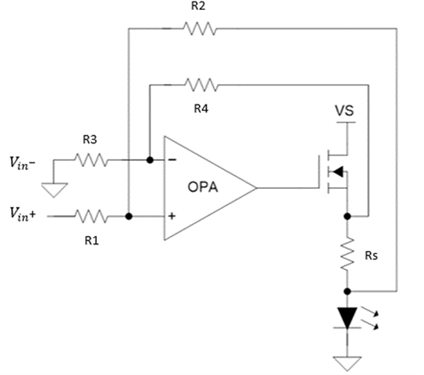
I assume that this configuration may be advantageous when a cathode grounded ("CG") laser diode is used. I came up with this explanation: For "CG" usually an additional differential amplifier or instrumentation amplifier is used to sense the voltage drop across shunt resistor Rs. It is my understanding that the Howland Current Pump with current boost transistor avoids this additional amplifier and as such might reduce the overall noise in the circuit (based on the "naive" thinking that a circuit using less active components exhibits less noise).

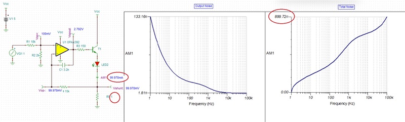
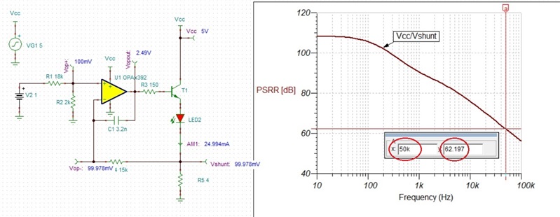
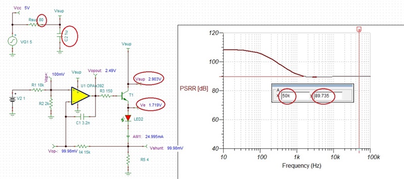
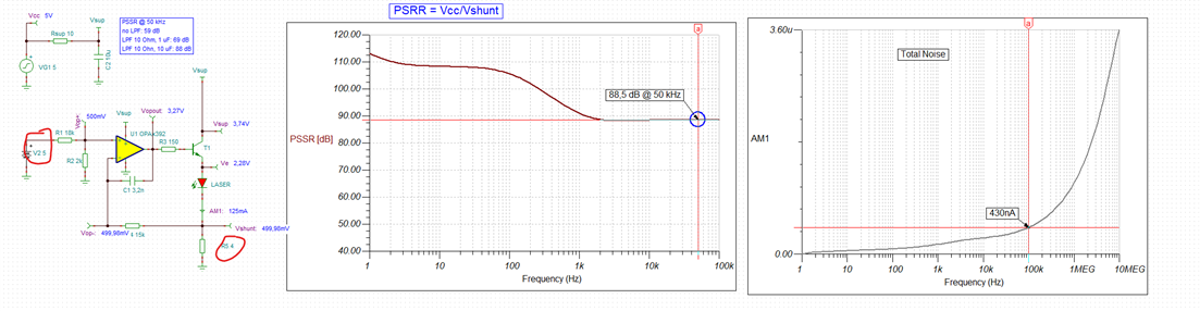
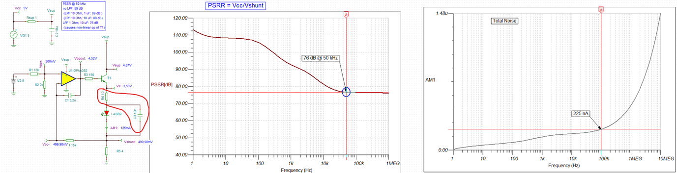
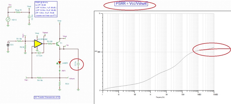
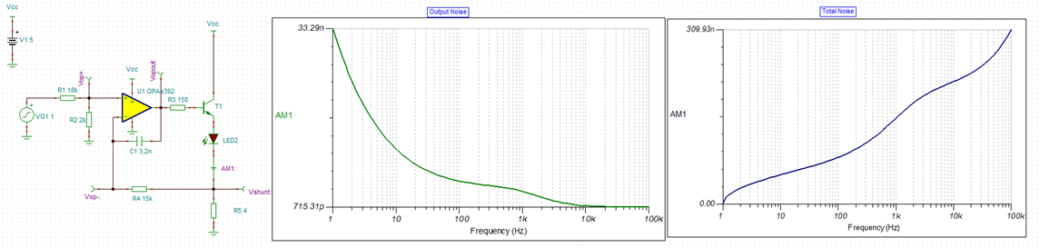
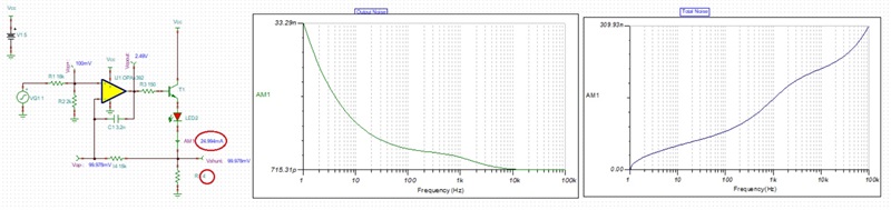
B) However, when the laser diode can be electrically "floating", the shunt resistor can be grounded and thus an even simpler circuit (see CIRCUIT060046) is usually suggested:

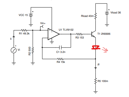
Note, I added the laser diode to this circuit in red. Here, R5 is the shunt resistor. Further, this circuit needs adaption to match the laser diode (e.g. remove Rload , adjust Vload, etc).

Regarding current noise, I assume that circuit B will perform better compared to circuit A.
However, I don't have much knowledge in the field and thus would like to know which design idea to follow to build a low noise driver.

Thanks.
Dan

  • Dan,

    For as long as T1 operates linearly (Vce> Vsat), Vload and Rload make no difference.  For the LED bias current of 100mA, the total current noise is about 3.56uArms - see below.

    You could move LED to collector resulting in slightly higher current noise - see below.

    If you wish to lower the noise, increasing the R3 base resistor to 10k lowers the LED total current noise to around 1.56uArms - see below.

    Below I have attached for your convenience Tina-TI schematic.

    OPA392 Low noise voltage-to-current converter.TSC

  • Hello ,

    That's awesome. Thank you for the work you have done to answer my question.

    I appreciate that you shared your Tina-TI file. I changed the circuit to match my target configuration (input voltage 0 - 5 V and Vcc = 5V) and now the noise figure is even below 1 µArms, see this screenshot:

    I attached the Tina-TI file below.

    Now these noise figures are impressive. However, the voltage source is ideal, I assume, it is like operating the circuit from a battery. In real life, this circuit will be powered by a DCDC converter that translates 24 V to 8V and a linear regulator that translates 8V to 5V. The DCDC converter will introduce additional noise that I might need to filter out. How can I simulate this noise of a DCDC converter?

    Thanks.
    Dan

    20 Low noise voltage-to-current (0-5V, 0-125 mA) converter.TSC

  • Dan,

    Your circuit has lower total noise NOT because of lower supply voltage but due to the fact that you lowered load current from 100mA down to 25mA - see below.   .

    If you bias the LED with 100mA, the total noise would be 900nArms - see below.

    Please notice that the total noise keeps increasing at higher frequency and thus the signal would have to be limited with LPF to get this value.

    As far as the DC-DC supply noise is concern, it would be best to use linear supply.  Having said that, the effect of the supply noise may be simulated using following circuit and determine PSRR rejection to be 62dB at 50kHz - this means that 1mVp supply noise would result in roughly 1uVp noise at Vshunt.

    One way to improve PSRR would be to add a low pass filter between Vcc and Vsup - see below.  Adding 80 ohms and 1uF increases PSRR to almost 90dB at 50kHz (see below). This means that 1mVp supply noise would now result in roughly 0.0316uVp noise at Vshunt (~32 times lower).  Please make sure you do not use higher than 80ohm Rsup for 25mA LED current since this may cause non-linear operation of T1 and OPA392 (below please see Vsup vs Ve).  

    20 Low noise voltage-to-current (0-5V, 0-125 mA) converter (PSRR).TSC

  • Hello Marek,

    Thank you for the detailed analysis and for providing your Tina-TI simulation file.

    I'm glad that you managed to include power supply noise in the simulation (PSSR graph). How did you generate the PSSR graph? I reproduced it by running "AC Analysis > AC transfer characteristic". After the graphs were plotted, I clicked on the post processing button and added a user function "VP_Vcc(s) / VP_Vshunt(s)". It looks like your graph and give roughly the same values. I hope that is the proper way as I don't know if there is another method.

    You noticed that I biased the laser diode with only 25 mA. Good catch. Its correct "working point" is at 100 mA which is achieved using an input voltage of 4 V. To give some headroom, the input voltage can be increased to 5 V which generates a current of 125 mA through the laser diode. See this simulation:

    So compared to your simulation, I increased the input voltage to 5 V and Rshunt to 4 Ohm (see red circles) to achieve the desired DC transfer result (Vin=0 - 5 V -> Ilaser= 0 - 125 mA). Also Rsup had to be reduced to 10 Ohm in order to make T1 operate linearly (Vce> Vsat), as you pointed out earlier. I increased filter capacitor C2 to 10 uF to make of for this.

    In this configuration PSSR is now at 88 dB @ 50 kHz (which is very similar to your result).

    Further you warned that "total noise keeps increasing at higher frequency and thus the signal would have to be limited with LPF to get this value."

    To see where the total noise is heading, I extended the graph to 10 MHz. Total noise reaches 3.6 uA in the simulation, see above.

    Now the question is: Where exactly would you place the low pass filter that you suggested?

    I tried the following (simulation file is attached below):

    I added a LPF in series with the laser diode, see red markup in the circuit. Due to the higher voltage Ve, I had to reduce Rsup further to 1 Ohm. This reduced PSSR to 76 dB @ 50 kHz.

    Adding the LPF reduced the total noise to 1.5 uA at 10 MHz, however, it does not limit the total noise to the value is has at 100 kHz. Total noise keeps increasing after100kHz.

    Where would you place the LPF to better limit total noise at higher frequencies?

    Thanks.
    Dan

    24 Low noise voltage-to-current (0-5V, 0-125 mA) converter (PSRR) + LPF.TSC

  • Your post-processing of PSRR is correct: PSRR=Vcc/Vshunt.  

    As far as limiting the noise bandwidth, I would place LPF across the LED and current setting resistor, R5 - see below.  I believe that the increase in the total noise above 10MHz is caused by inaccurate modeling of the open-loop output impedance (Zo) and therefore is not real (see at the bottom).

    24 Low noise voltage-to-current (0-5V, 0-125 mA) converter (PSRR) + 2LPF.TSC

  • Thanks, , for the explanation of the increase in total noise. In summary I understand that the steep increase of noise above 10 MHz might be a TINA-TI quirk and I should ignore it.

    That's basically all I understood from your op amp output impedance test. Whatever you did to figure out the problem, is there an application note that explains it?

    And when I replace the OPA392 with a different op amp, should I just ignore any noise above 10 MHz as before?

  • Hi Daniel,

    Marek is out at the moment.

    I don't think we have any specific app. note for this exact circuit but filtering at the output is covered on the noise section of our Precision Labs videos:

    https://www.ti.com/video/series/precision-labs/ti-precision-labs-op-amps.html

    Basically, the amplifier will only offer limited noise suppression ability.  A discrete filter directly at the output can always help reduce noise at very high frequencies.

    Regards,
    Mike

  • Hi ,

    Thank you for getting back to me. I watched the videos about noise. Guess I have to watch them all over again to comprehend the topic.

    Nevertheless they do not seem to discuss the issue the Marek mentioned above. That is the increase in the total noise above 10MHz in the simulation result.  He wrote that this may be "caused by inaccurate modeling of the open-loop output impedance (Zo) and therefore is not real (see at the bottom)". This kind of erodes my trust in the simulation results. How can I tell what is real and what isn't? As I'm quite a newbie to this topic I used the simulation to improve the circuit regarding noise and now I learnt that the results may not even be close to the real circuit. How do I handle this? Should I assume that the noise value at, e.g., 10 MHz is the maximum total noise of the circuit and just ignore the increase above 10 MHz?

    Thanks.
    Dan

  • Hi Dan,

    I don't mean to dismiss this as a basic topic, I just wanted to be sure you were aware of the noise presentations.  Actually this is a tricky problem.

    Eventually, the output impedance will start to fall over frequency, because the parasitic capacitance from the output devices will be the dominant impedance.   The output impedance forms effectively a resistor divider from the gain of the op-amp - so, if the output impedance stays flat or goes up over frequency, you will never get a reduction in noise density, and the total (integrated) noise will continue to increase across frequency.   I do believe the OPA392 model could be improved by eventually having the output impedance begin to drop at very high frequencies.  But, I would not rely on the model to give you accurate noise results at 100 MHz for a 13 MHz amplifier  - we typically only characterize the model behavior up to 2-3X the bandwidth of the amplifier.   We do have measurements of output impedance that we use for the simulation, but these will be for only one condition, and will not take into account output current or supply changes.

    For this reason, you will certainly have better attenuation if you can use an external R/C circuit.  Are you able to add the capacitor that Marek mentioned or will that be a problem for your circuit?

    Regards,
    Mike