Other Parts Discussed in Thread: TINA-TI
Tool/software:

dear:
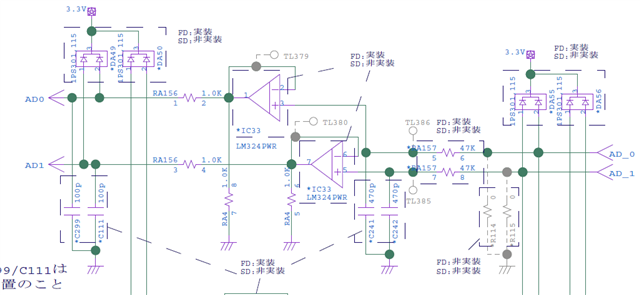
can you help me。LM324PWR application circuit is shown in the figure above。
we want to simulation its gain margin/phase margin。
how to build simulation circuit。
please give me some help。
This thread has been locked.
If you have a related question, please click the "Ask a related question" button in the top right corner. The newly created question will be automatically linked to this question.
Hello,
We have videos series under TI Precision labs to help guide on stability simulation. The videos specifically show how to set up and post-process in TINA-TI.
Please see the following videos:
https://ti.com/video/4080288067001
https://ti.com/video/6341906518112
Please let me know if you have further questions.
Thank you!
Regards,
Ashley
dear Ashley
thank you for your reply。
I have watched the video,but i have a question。
Why disconnect the loop? The actual loop is closed loop, is it not more suitable to simulate the actual loop directly。
Hello user6483709,
The reason we run open loop analysis is due to the mathematical definition of what causes instability.
Acl = Closed loop Gain
B = Feedback factor
Aol = open loop gain
Aol*B = loop gain.
The relationship between the closed loop gain and the open loop gain is such:
Acl = Aol/(1+Aol*B)
So going back to what causes instability, if Aol*B = -1 then Acl would be undefined as the denominator would be zero. So when we run stability analysis we are looking for when Aol*B = -1. The two parameters left are Aol and B, hence why we want to open the loop to see Aol.
This is covered in more detail in the Stability - 2 video.
Hope this helps!
Best Regards,
Robert Clifton