This thread has been locked.

If you have a related question, please click the "Ask a related question" button in the top right corner. The newly created question will be automatically linked to this question.

PGA855: Amplifier shows ringing/instabilities with 3 MHz input signal

Part Number: PGA855
Other Parts Discussed in Thread: ADS8900B,

Tool/software:

Dear TI support,

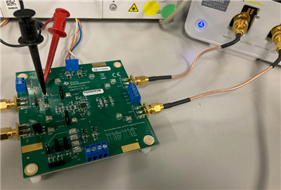
In our custom data acquisition evaluation board we observed some unwanted behavior for signals with a few MHz. We tracked it down to the used PGA855 amplifier. For certain frequencies and signal strengths the amplifier becomes instable and produces ringing effects on the output signal. To ensure this is not caused by our design, we also bought the evaluation board of the PGA855 and are able to reproduce the same faulty behavior.

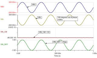
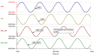
Here are 2 results of the PGA855 evaluation board supplied with +/-5V dual supply, 1Vpp input signal and Gain 1:

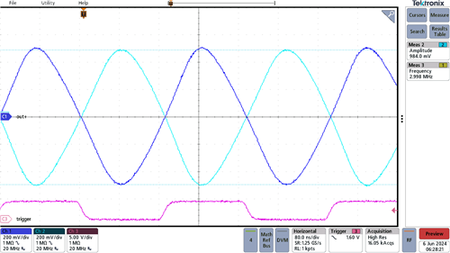
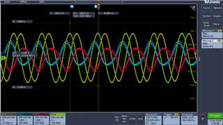
With 3.5 MHz we see a little ringing on the output signals (red, blue)

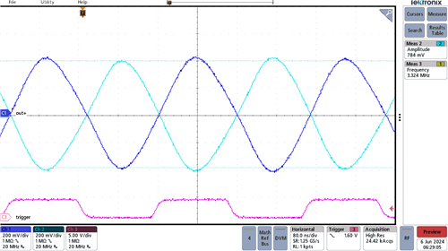
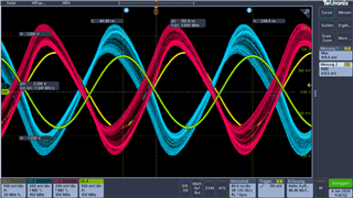
With 3 MHz we see a massive ringing on the output signals (red, blue)

Is this a (known) problem of the amplifier? Is this in any way related to the revision history of the datasheet where the maximum sampling rate was reduced from 4 MSPS to 1 MSPS?

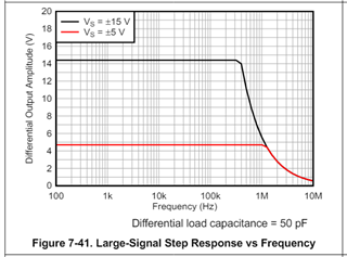
But that doesn't actually makes sense because there was no change in the allowed input bandwidth (which should be 10MHz) but only in the sampling speed of an external ADC. What is meant by this reduction anyway - why shouldn't I be able to digitize the amplifier output signal with any speed I want to?

If you can confirm this behavior are there any plans for an errata of the datasheet or a new silicon revision of the PGA where this behavior is fixed?

  • HI Martin,

    The PGA855 has no reported issues, nor revisions related to performance. The device offers flat frequency response to 10-MHz as shown on the first page of the data sheet. 

    Regarding the data sheet Revision A to Revision B; this is an editorial revision executed one day apart and not related to the device performance; both data sheet revisions took place on the same week in September 2023, about one to two days apart. The PGA855 is a 10-MHz BW device, and can drive un-buffered a high resolution, 20 Bit SAR ADCs at 1-MSPS (conservative) as shown on the application example 9.2.2 ADS8900B 20-Bit SAR ADC Driver Circuit. To put things into perspective, an amplifier will require a much higher bandwidth than >10MHz to drive an high-resolution (16Bit to 20Bit) un-buffered SAR ADC at 4-MSPS.  

    A few questions to reproduce the issue:

    -   Please provide the output R-C-R filters and feedback compensation capacitors are use in this test? If possible please provide the schematic of your design.

    -   What device or load is connected at the PGA855 output? are there any BNC or coaxial cables connected to the device outputs directly without isolation resistors 

    -   What are the voltage supply conditions: VS+, VS-, LVDD, LVSS, VOCM.

    -    PGA Gain?

    -   Input Signal: Input common-mode voltage (DC) voltage where the signal is centered to with respect to the PGA855 GND; signal amplitude

    Thank you,

    Best Regards,

    Luis Chioye

  • Here are the answers to your questions:

    -   The output filter is default on PGA855EVM, the feedback compensation is open. 

    -   The outputs are directly connected to the oscilloscope with coaxial cables (RG316). 

    -   VS+: +5v, VS-: -5V , LVDD = VS+, LVSS = VS-, VOCM = 2.5V.

    -    Gain = 1

    -   Input Signal: Input common-mode voltage (DC) voltage: 0V; signal amplitude = 500mV (1Vpp)

    As said the problem should be easily reproducible with the eval-board (except we made some basic mistake).

  • Hi Martin,

    Performed measurements with a couple of PGA855EVMs. On this setup, I used a 2-channel waveform generator (Agilent 33500B) to generate the 3MHz and 3.3MHz fully-differential signal. The PGA855EVM was left un-modified with the input and output default filters, which have a corner frequency of ~7.57MHz. The OUT+ and OUT- PGA855EVM SMA connectors where connected to the oscilloscope via very short ~5.9" coax cables. I used the same supply conditions as above, with VOCM=2.5V and bipolar supplies ±5V for the input and output stage; and the signal was 1vp.

    I used the function generator SYNC output to trigger the oscilloscope on CH3.

    Attached are the oscilloscope plots for 3MHz and 3.3MHz.  There is some subtle attenuation due to the corner frequency of the default filter, but these can be adjusted per the application requirements.

    Vout+ and Vout- with an input signal at 3MHz. CH1 OUT+, CH2 OUT-, CH3: Function Generator SYNC

    Vout+ and Vout- with an input signal at 3.3MHz.


     What is the length of the coaxial cables used on your setup? And what is the capacitance spec for these coaxial cables? Instrumentation amplifiers and precision amplifiers can be sensitive to capacitive loads, and it is common to see issues related to stability or marginal stability while driving coaxial cables. It is quite possible that the PGA855 has marginal stability or low-phase margin IF driving large capacitance or long coaxial cables on the setup. Marginal stability/low phase margin can cause excessive ringing.

    Thank you and Best Regards,

    Luis

  • HI Martin,

    Although this is not related to the instability in the measurement shown, it is worth noting that a differential output amplitude of 2Vp, and frequency of 3MHz, the PGA855 may be right at the edge of the large signal response vs frequency.  See figure 7-41 below. 

    Thank you and Regards,

    Luis

  • We will check our cable lengths and reduce them. Then if we can properly reproduce the issue we will take some pictures or record a video to hopefully resolve it.

  • Thank you, here is a picture of the short SMA-BNC adaptor cables used to test one of the PGA855EVMs while connected to the oscilloscope.

    Alternatively, you could consider low capacitance oscilloscope probes, input impedance: 10 MΩ || 12 pF


    Thank you and Regards,

    Luis

  • Okay here we go with our little video to reproduce the issue in an easy setup with a short cable assembly. We recognized today that the phase of the input signals at 4 MHz is absolutely decisive, whether the instability occurs or not:

  • Okay I needed a couple of tries to convert the video in a playable format but now it works.

  • HI Martin,

    1) If you see marginal stability while driving the coaxial cables and oscilloscope, a quick experiment would be to use the low capacitance probes ~12pF that you have used at the inputs, and place them to monitor the outputs and see if stability improves. Depending on the equipment, each of the oscilloscope inputs can add up to 50pF load each, and the coax cables may add other few 10s of picoFarads of capacitive load.

    2) I also suspect, the behavior observed is greatly in part due to the common-mode rejection degradation of the instrumentation amplifier at high-frequencies, when you are applying a 30-degrees of phase error at the input signal at 4-MHz.

    The differential input voltage (VIN_DIFF) is the difference of the input terminals:

    VIN_ DIFF = ( IN+) - (IN-).

    And the common-mode input voltage, (VIN_CM) is the average or common-mode voltage at the inputs:

    VIN_CM = [(IN+) - (IN-) ] /  2

    When you apply two inverted input signals at 4-MHz, with perfect 180-degrees of phase, you are applying a purely 1V differential input signal; and no common-mode signals (0V).

    See ideal SPICE transient simulation below, it calculates the input differential and common-mode, where the differential and common-mode voltage component is simulated/calculated for a 4-MHz 180-degree out of phase input signals. When using 180-degrees out-of-phase signals, there is no input common-mode voltage component.

    However, when you inject two input signals at 4-MHz, with ~150-degrees out of phase difference, you are now applying both a differential signal component of 964mVpk at 4-MHz, and also a significant 4-MHz common-mode voltage component of ~130mVpk (15% of the signal):

    The PGA855 precision instrumentation amplifier, as most instrumentation amplifiers in this class will offer high-common mode rejection at DC and low frequencies. At DC to 60-Hz the data sheet specifies around 82dB (min) and 120dB (typ).

    The CMRR will degrade significantly as expected at high frequencies at the 4-MHz range, since the amplifier only has a limited 10-MHz BW. At PGA Gain=1, 4-MHz CMRR is in the area of ~25dB typical (in contrast to 120dB typ at DC), and the minimum CMRR at 4-Mhz can be lower as there is no minimum spec at 4-MHz frequency; so you will likely see a significant error added into the signal. Please see figure 7-24

    In your application, do you expect to inject signals with out-of-phase mismatched by 30-degrees at 4-MHz?  This is a large phase error. In general, for differential amplifiers, we recommend using very symmetrical and good matching on the board layout and components at the positive and negative paths to avoid common-mode errors; and phase mismatch errors.

    Thank you and Regards,

    Luis