Other Parts Discussed in Thread: LM2904LV-Q1, LM2904B-Q1, TL082
Tool/software:
Hi expert
Could you please help me review the schematic? I look forward to hearing from you soon.
Best Regards!
Mason
This thread has been locked.
If you have a related question, please click the "Ask a related question" button in the top right corner. The newly created question will be automatically linked to this question.
Tool/software:
Hi expert
Could you please help me review the schematic? I look forward to hearing from you soon.
Best Regards!
Mason
Hi Clemens
Thank you for your reply. I don't know what you mean, I'm not very familiar with this material. Could you describe this in more detail? Thank you.
Best Regards!
Mason
Hi Clemens
The attached is the TL082 circuit diagram, and there is an op amp that is not used. Therefore, the customer's side is connected to the voltage follower, Could you please help me to confirm whether it is OK.
Best Regards!
Mason
See section 5.4 of Understanding Operational Amplifier Specifications. The TL0xx cannot measure a voltage that is near VCC−; you need a different opamp.
Everything else (unused amplifier, decoupling) looks OK.
Hey Mason,
I agree with Clemens' comments. Additionally, this topic is explained in the following TI precision labs video https://www.ti.com/video/4620557492001
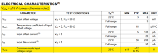
This specification is called input common-mode voltage. This is range of input voltage where op amp output voltage will behave linearly.

In the Electrical Characteristics table, with +/-15V supply, linear input voltage range is 15V (V+) to -12 (V- + 3V). This means that V- is not in the linear operating range of the op amp.
Best,
Jerry