Other Parts Discussed in Thread: TLC27M2, TLV2170, TLV3702, TLC3702, LMC6762
Tool/software:
Hi ti team,
Firstly, build an open-loop comparator using TLC272IDR, where the 2PIN of the IC is used as the sampling pin, the 1PIN of the IC is used as the output pin, and the 3PIN of the IC is the reference source with a voltage of 2V, and the power supply VCC is 4V. As shown in the figure below.
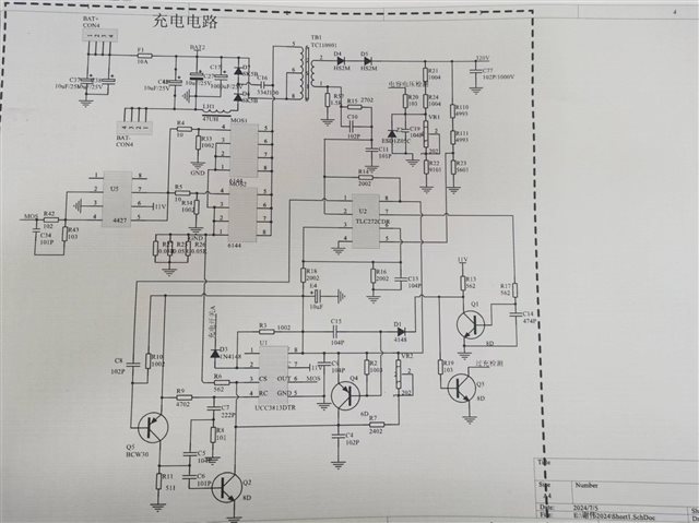
Secondly, currently, there are two Top Side situations when using TLC272IDR. For the same PCB board, different Top Sides result in different outputs. What is the cause of this phenomenon? After observation, TLC272IDR has undergone changes in DFAB. Is it caused by this change?As shown in the figure below.

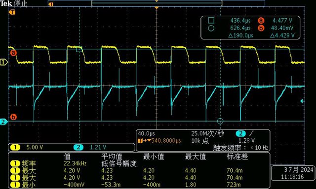
Top Side is BCM,Channel 1 is IC 1PIN, and Channel 2 is IC 2PIN.
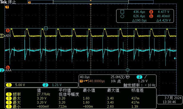
Top Side is 38K,Channel 1 is IC 1PIN, and Channel 2 is IC 2PIN.