Other Parts Discussed in Thread: AMC3301
Tool/software:
Hello,
In testing several new PCBs using this device, a fraction of the circuits exhibit instability, which is shown in the attached video. The trace is DCDC_OUT (high side) with respect to HGND. and it alternates between a stable 3.6V and the oscillation that appears to range form 200uS to 400uS, and has a P-P of ~1V (vertical scale is 2V/division). Whenever this oscillating waveform is observed, the outputs OUTP and OUTN flop aroiund randomly. This occurs even when INP = INN = HGND.
We already know that our design has two deviations from the recommendations in the data sheet:
1. We missed the 100nF capacitor on HLDO_IN (C1 in Figure 10-1 in the data sheet
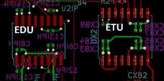
2. Bypass capacitors are on the opposite side of the board and vias are used.
3. Bypass capacitors are not the recommended parts. One of them on DCDC_OUT is rated for 10V, and they are all 0402.
I have added a 100nF capacitor between pins 3 and 2 right at the device, and the instability continues, though I think it takes less time now to stabilize.
So how bad are these "violations?" Has this been observed in other designs, and are there any recommendations, other than a full re-spin with layout per the data sheet?
Regards, Frank LaRosa