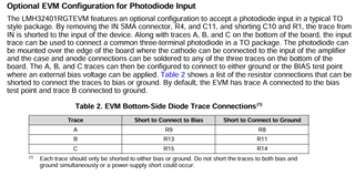
Tool/software:
I purchased the LMH32401RGTEVM Evaluation Module from Texas Instruments and plan to use it with a Hamamatsu photo detector (model G9801-22). To mount the photo detector on the board, I followed the user guide for the LMH32401RGTEVM Evaluation Module and removed the input SMA connector, as well as the R4 and C11 components.
I have connected the cathode of the photo detector to the input, the anode to the A terminal on the board, and the case to the B terminal. I applied a 3.3V voltage to the board and a +5V voltage to the BIAS terminal of the photo detector, while connecting the remaining lead to the GND next to the EN pin.
Additionally, the user guide mentioned that C10 and R1 should be shorted. I checked the circuit and it seems that C10 and R1 are already shorted. Is this correct?
For clarity, I have attached a photo of the relevant section of the user guide.
However, the system does not seem to be working correctly. Could there be something I missed or done incorrectly?
For reference, here is the link to the photo detector's information: Hamamatsu G9801-22.