Other Parts Discussed in Thread: OPA320
Tool/software:
Hi TI expert,
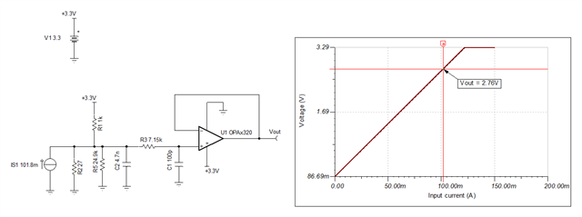
In TIDM-2014, Could you please explain the circuit below:
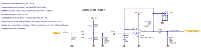
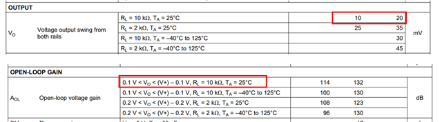
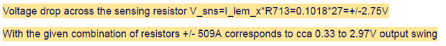
Why Voutput is in range 0.33 to 2.97V?
Thank you
Tool/software:
Hi TI expert,
In TIDM-2014, Could you please explain the circuit below:
Why Voutput is in range 0.33 to 2.97V?
Thank you