Tool/software:
Hi team,
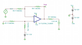
In the following circuit, when Vin inputs a steady-state voltage or a sine wave, Vout will oscillate. I have suggested customers before that it is caused by the output capacitive load. Reducing C65 or increasing R24 can solve this problem.

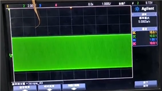
I tried several different boards at that time and found that the parameter threshold that caused the oscillation was not fixed.
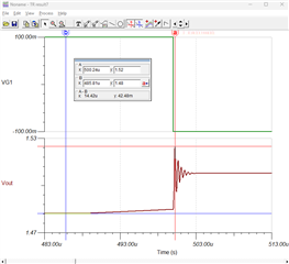
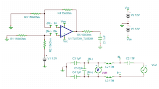
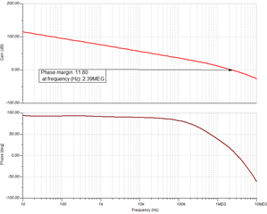
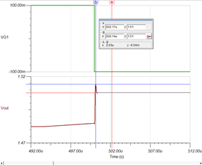
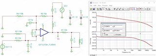
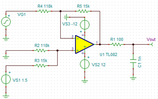
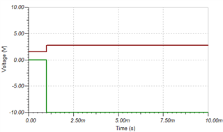
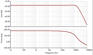
The problem now is that in the new designs, in order to confirm in advance whether it will cause output oscillation, I want to use simulation software such as TINA to analyze the rationality of the design parameters. However, I modeled the circuit parameters that will cause oscillation and input a -10V step signal, but it did not produce abnormal oscillation in the simulation results.
May I ask: 1. Why can't the following model reproduce the oscillation?
2. In addition to actual measurement, is there any simulation method that can reproduce the oscillation?
Thank you!
Regards,
Maggie


