This thread has been locked.

If you have a related question, please click the "Ask a related question" button in the top right corner. The newly created question will be automatically linked to this question.

TIPD155: XTR300

Part Number: TIPD155
Other Parts Discussed in Thread: XTR116, XTR300, , XTR305, DAC8563

Tool/software:

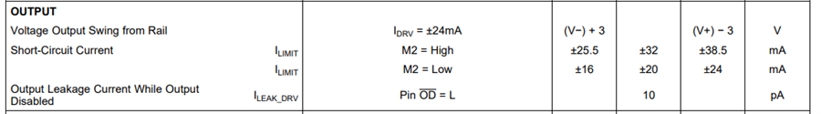
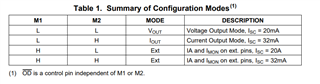
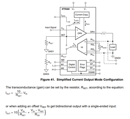
Looking to see absolute maximum current output capability of the XTR300. The XTR116 discusses how to increase maximum output current with parallel resistor to increase maximum output current to 45mA (max).

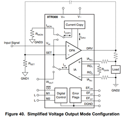
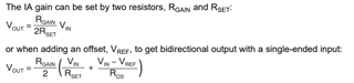
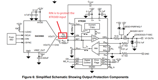
Can the XTR300 support +/-40mA current output capability? If so, is there an equivalent modification to the reference design (TIPD155) to achieve this?

  • Hi Jeffrey,

    The XTR116 (2-wire current transmitter) uses a very different topology than the XTR300 (3-wire current transmitter). 

    The XTR116 is a 2-wire current transmitter, where most of the current flows through an external NPN bipolar transistor, and its possible to place resistors in parallel with the internal RLIM resistor to extend the output current to a maximum current of less than <45mA.  Nevertheless, the device linear range for the XTR116 is specified for the span from 250uA to 24mA.

    The XTR300 is a 3-wire current transmitter that does not require an external transistor.  All of the output current flows to the output stage of the XTR300, and the linear range is specified up to ±24mA.  If you set M2=High, the current limit is typically ±32mA, but can vary across devices with a minimum of ±25.5mA to a max ±38.5mA.


    A discrete voltage-to-current circuit could be implemented using a discrete amplifier for a range of ±40mA, but the XTR300/XTR305 current transmitter devices are specified for accuracy at the ±24mA range.

    Please let me know if you have questions.

    Thank you and Kind Regards,

    Luis 

  • Thank you for your quick response. Looking at TIPD155 Reference Design, it uses DAC8563 (Dual 16-bit Buffered Voltage-Output DAC). I noticed that it drives a series resistor to convert to current at the VIN input. Can a current-output DAC be used to directly drive the VIN of the XTR300 without the series resistor? If so, can it still support both current and voltage output modes?

  • HI Jeffrey,

    Yes, the XTR300 is a 3 -wire current transmitter, or voltage output driver.  The device can be configured as current output or voltage output by the digital I/V control select pin as shown on Table 1.

    The XTR300 requires an input voltage at the VIN pin 3.  This is true for both output current mode, or output voltage mode.  

    Figure 40 on data sheet page 19 shows the standard voltage mode, and transfer function as a function of the RGAIN, RSET (and ROS) external resistors and VIN input voltage:

    Figure 41 on data sheet page 20 shows the standard current mode, and transfer function as a function of the RSET (and ROS) external resistors and VIN input voltage.

    Looking at TIPD155 Reference Design, it uses DAC8563 (Dual 16-bit Buffered Voltage-Output DAC). I noticed that it drives a series resistor to convert to current at the VIN input. Can a current-output DAC be used to directly drive the VIN of the XTR300 without the series resistor? If so, can it still support both current and voltage output modes?

    The XTR300 requires an input voltage at the VIN pin (this is different than the XTR116, which requires an input current). During normal operation, once the XTR300 is properly powered up, the XTR300 output is a function of the VIN voltage.  During normal operation, the current across RIN is very small.  The input bias current flowing through the RIN pin is only the input bias current of the op-amp, around ±20nA typical, ±35nA maximum.  

    Nevertheless, as you have correctly mentioned, TIPD155 recommends a series resistor at the VIN pin. The series resistor at VIN is used for input protection purposes.  Since the DAC is powered with a 5.5V supply, and the XTR300 is powered with a separate bipolar ±15V supply, the RIN resistor is only used to protect the XTR300 VIN input during the power-up/power-down sequences, or essentially protect the device during a fault event where the DAC is turned on, actively forcing voltage, but the XTR300 power supply is still turned off. This is done to ensure the input current during this fault condition is limited to a couple of milliamps to prevent  damage to the XTR300.


     Thank you and Kind Regards,

    Luis