This thread has been locked.

If you have a related question, please click the "Ask a related question" button in the top right corner. The newly created question will be automatically linked to this question.

TLV2372-Q1: open loop output impedance

Part Number: TLV2372-Q1
Other Parts Discussed in Thread: OPA994

Tool/software:

Hello team,

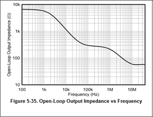
I am looking for the open loop output impedance for the TLV2372-Q1.

I have been searching existing threads and found this one here: https://e2e.ti.com/support/amplifiers-group/amplifiers/f/amplifiers-forum/499078/what-is-the-tlv2372-open-loop-output-impedance

But the output impedance is quite high, round about 30k. Similar Op Amps, where this value is given in datasheet, are in the range of 500-1000Ohm.

Can you confirm the 30k ?

Thanks and best regards,

Michael

  • Hey Michael,

    I believe this information is correct. It is not unheard of to have higher Zo at low frequencies. The output impedance is based on the architecture of the output stage. It is not listed in the

    Usually this is because of specific reasons. For example, the OPA994 has a similar Zo which is due to the compensation scheme that is implemented that allows it to drive large capacitive loads.

    Best,
    Jerry

  • Hi Jerry,

    thanks for checking.

    So this op amp should be stable with 249R und 1µF at the output. Symmetrical supply voltages assumed.

    Can the stability be checked under this conditions with TINA TI?

    Thanks,

    Michael

  • Hey Michael,

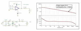
    The configuration of the amplifier can introduce other factors that can influence the stability of the loop, but for a hypothetical unity-gain circuit as pictured below, there seems to be sufficient phase margin. In practice, the customer circuit will have IN+ and (IN+) shorted, and the circuitry below it will not be there, this is there just to analyze the circuit in an open-loop configuration. For more info on why this is done, please see the TI Precision Labs Video on Stability: https://www.ti.com/video/series/precision-labs/ti-precision-labs-op-amps.html?videoId=6341906518112 

    TLV2370_Stability.TSC

    I've provided the TINA file that I used to simulate this. If the customer circuit is implemented differently, this can be changed in the TINA file and the AC sim can be rerun.

    There is no differential capacitance specified in the datasheet, so a small value was added, but it is almost certainly not correct (a guess). This will not greatly change the stability analysis in most cases.

    Best,
    Jerry

  • Thanks for providing the model. We will play around with it and verify the customer circuit with it.

    Best regards,

    Michael

  • Michael,

    Happy to help! Please note that the model provided in the above TINA schematic is just the AOL and Zo. There are no clamping structures and the device will not function properly in transient operation. This model is only for AC analysis.

    Best,
    Jerry