This thread has been locked.

If you have a related question, please click the "Ask a related question" button in the top right corner. The newly created question will be automatically linked to this question.

OPA189: OPAx189 as a LPF buffer

Part Number: OPA189
Other Parts Discussed in Thread: OPA387, TINA-TI, , OPA182, OPA187, DAC8831

Tool/software:

Team,

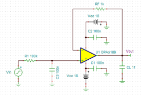
I am considering using the OPAx189 as a low-pass filter buffer.  This would just be a resistor and capacitor LPF, with an OPAx189 as a unity gain buffer on the output.  For this example, suppose the resistor is 100kOhm and the capacitor is 0.1uF C0G.  This would have a cutoff frequency of 15.9Hz.

Here are two questions about this circuit:

1. Our 100kOhm resistor is much larger than the recommended maximum input impedance of the OPAx189 (1kOhm, from SBOA586) to prevent noise and offset issues with charge injection ("chopper noise").  However, at the 150kHz chopping frequency, the input impedance drops to 10.6Ohms due to the capacitor.  Is this arrangement going to have issues with chopper noise, or is the input impedance calculated at the chopping frequency for the purposes of the maximum?

2. Will there be any "integrating" effect done to the charge injection noise by the capacitor?  Would one be more prominent if the filter cutoff is closer to the chopping frequency (let's say 15kHz instead of 10Hz)?

Thanks,

Jack Terrell

  • Hi Jack, 

    I assumed that you have read the following article. 

    https://www.ti.com/lit/wp/sboa586/sboa586.pdf

    Per your description, the LPF's cutoff frequency is very low at 15.9Hz, and you are likely concerned about 1/f noise, not the broadband noise. If it is low voltage chopper amplifier, you may select OPA387. The chopping frequency is nearly 4 decades after the LPF frequency and the "chopping noise" effect will be attenuated by nearly 80dB or more, so this should not be your concerns (also the chopping noise is a very weak harmonic noises and attenuated by additional 80dB will be insignificant noise, and it is not even within the bandwidth of your application interest.). 

    OPA387 LPF 09172024.TSC

    If you have other questions, please let us know. 

    Best,

    Raymond

  • Raymond,

    Thank you for responding, but I'm not sure if the question was completely understood.  I understand that a 15.9Hz after the OPAx189 (or OPAx387) would attenuate the chopping noise very well, and the 1/f noise will be very good (as with all chopper circuits), but the question is about if the filter is prior to the OPAx189.

    From what I understand, the output stage of the chopper amps is pretty standard, and the input stage is the unusual part.  The main question is about how the input stage would respond to the capacitor.

    I understand the behavior of a chopper followed by an LPF, but I haven't seen many examples or specific recommendations on an LPF followed by a chopper, for example to get a low-impedance low-bandwidth output with no 1/f noise and a miniscule offset.  The application of this circuit is to buffer a DAC, to reduce broadband noise, but with low output impedance.  The DAC may be an unbuffered DAC, buffered by another chopper prior to the signal entering this circuit.

    I have been able to do some tests in TINA-TI (file attached), and they show that noise is mostly dependent on parallelled value of the feedback and input resistances, as suggested in SBOA586.  The main thing driving issues with noise spikes was a large feedback resistor (100k+).  However, I wasn't able to reproduce the funky pattern above the chopping frequency from the datasheet's noise spectrum, so I'm sure that the noise is simplified in some way.

    Thanks,

    Jack Terrell

    sbomaf0d_mod_09182024_jack.TSC

  • Hi Jack, 

    Op amp is unable to drive capacitive load without compensation. The CL in the simulation is in fF or pF, which may be acceptable, if an op amp is driving such capacitive load. As soon as the capacitive load is greater than 100pF or large, you have to check for the loop stability. Without proper op amp loop compensation, op amp may oscillate at the output (instability issues).

    The application of this circuit is to buffer a DAC, to reduce broadband noise, but with low output impedance.

    If the application is buffering the DAC, then the option is to buffer and perform post LPF after the OPA189/OPA387's output stage. I need to know what the op amp is driving at the output stage. 

    You can use op amp as active filter such as SallenKey or MFB 2nd order filter with some of op amps. This is an option that you are able to filter out any unwanted noise or frequency region out of your application. 

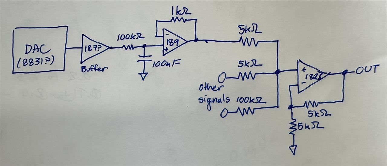
    Can you send me a schematic or drawing how you are going to filter out DAC signal? If you are think about the op amp configuration above, it may not work.

    If you put 100kΩ/100nF after DAC's output terminal, it may or may not have the current to drive the LPF. So it is easier to buffer the DAC signal first, then filter it out.  

    Best,

    Raymond 

  • The 1fF (0.001pF) was to essentially "delete" the capacitor CL, which was initially set to 15pF in the original file downloaded from the OPA189 page.  It should essentially do nothing.

    I don't have much doubt about driving the 100kOhm filter.  At worst case, this would only require less than 1mA in output current, and the DAC would just be buffered (say, by another OPA189, OPA182, or OPA187 if it's higher impedance).  If I wanted to be really cheap, I could even put the DAC output into the RC filter without buffering and just account for its output impedance (not great for precision of cutoff frequency, but good enough for a lot).

    The output of this amp would be to act as an offset in a summing amplifier downstream.  The output needs to be pretty low-impedance for the summing ratio to remain accurate.  I don't want to filter the entire sum, just the DAC offset.

    OPAx189 Schematic

  • Hi Jack,

    This drawing is much clearer! 

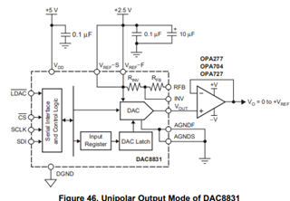
    The DAC8831's output should be connected to a buffer as the datasheet indicated. It looks like that the DAC may be able to drive the LPF, but it will be better option to have buffer after DAC output. 

    I don't want to filter the entire sum, just the DAC offset.

    Your schematic looks ok. I would match all R2, R5 and R6 to 5kΩ, which it will be easier to calculate and avoid the summing errors. 

    1411.OPA387 LPF 09172024.TSC

    If you have other questions, please let us know. 

    Best,

    Raymond