This thread has been locked.

If you have a related question, please click the "Ask a related question" button in the top right corner. The newly created question will be automatically linked to this question.

OPA2191: Discrepancy in simulation result

Part Number: OPA2191

Tool/software:

Dear Team,

I was simulating a circuit which contains all AD parts.

I found the the alternate TI parts and started simulation in tina ti .

The results I obtained in both simulations are entirely different .

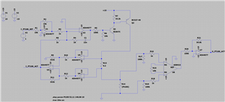
Circuit Diagram in LTSPICE
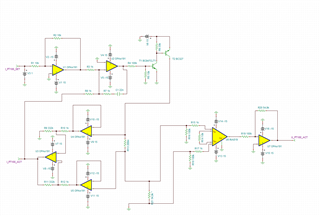
Circuit Diagram in TINA TI
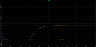
OUTPUT waveform LTSpice
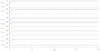
OUTPUTwaveform TINA
I am also attaching the tina simulation file here.

I_PT100_SET is the input signal coming from a DAC.For simulation purpose I set it as 1V

I_PT100_ACT is fed to an adc of stm32

Pt100 - autosave 24-10-02 11_09.TSC

Regards

HARI

  • Hari,

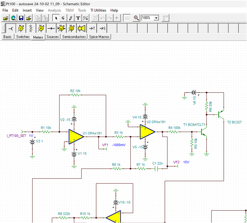
    Op amp U2 in the tina circuit does not have a DC feedback path.  Is this what you intended?  I think this is the source of the simulation issue.  If it is what you intended, can you explain the purpose of the circuit?  In the excerpt below you can see the DC operating point is railed.  

    Best regards, Art

  • Hi Kay,

    Thank you very much .

    This is a circuit given to me by our customer for simulation and cost reduction.

    The circuit is a PI controller. The capacitor C1 is blocking the DC.

    I think if I put a resistor parallel to C1 will solve this problem.But how to design the value,I don't know.

    The same circuit is working in LTspice.I used the AD parts in that simulation.Which my customer was using.

    May I know how to make this circuit working in Tina.

    If you don't mind could you please tell me why it is working in one simulator and not in other

    I imported the TINA TI Spice models to LTSPICE and the expected result is coming but there is a peaking initially

    Please see the below image.

    Regards

    HARI

  • Hi Hari, 

    Art is on business travel and will respond when he returns. We will need approximately 3 business days. 

    Best Regards, 

    Chris Featherstone

  • Hi Chris,

    Thank you for the info.

    Regards

    HARI

  • Hari,

    Sorry for the delay in response.

    • I think the issue is that V7 power supply has the wrong polarity.  Nevertheless, I think that using the "practical integrator circuit is a good idea".  Please check the attached document with the polarity fixed.
    • The feedback resistor in parallel with the integrator capacitor is normally set to a very large value (e.g. 1Mohm).  This would set the dc gain to a very high value of 1M/1k +1 = 1000V/V.  Basically, the integrator would act as the same as if this resistor is not in the circuit for most of the frequency range.  At very low frequencies, the gain of the practical integrator would flatten out to 1000V/V whereas the gain of the integrator without the feedback resistor would continue to increase until it reaches the DC AOL of the op amp.  
    • In most cases I think it is good to use the practical integrator topology not only for simulation but also for the actual circuit.  Some integrator circuits will have issues in the lab where the circuit saturates.

    Pt100 -fix polarity.TSC

    Best regards,

    Art

  • Hi Kay,

    Thank you very much.

    You are  correct V7 polarity was wrong.

    Will provide a provision for practical integrator.

    Regards

    HARI