LMH6703: Simulation with PSpice for TI and LTSpice

Part Number: LMH6703
Other Parts Discussed in Thread: THS3491

Tool/software:

Dear Technical Support Team,

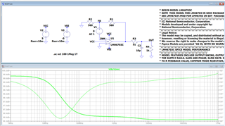
I'd like to confirm to use ADI's method with LTSpice, but it seems not to work for open loop gain(FB/INM).

The gain results in a gain of no less than 0 dB and I am unable to confirm the phase margin.

Is the problem due to the construction of the SPICE model?

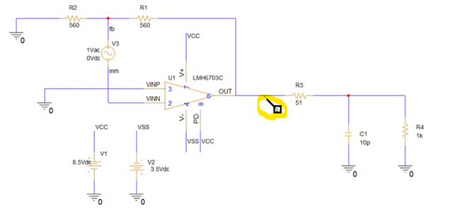
In LTSpice, the phase margin is measured as V(fb)/V(inm), where fb is the + side of the ideal power supply (AC) that is placed in the middle of the feedback line and inm is the - side.

www.analog.com/.../5579254320001.html
In PSpice for TI, I think I should use the output of the op-amp as the observation point as shown in the video, but in this circuit, is it correct at the end of the resistor (51Ω)?

Do you have example design of LMH6703 simulation(GAIN and phase margin) with PSpice for TI?

www.ti.com/.../ti-precision-labs-pspice-for-ti.html


Any advice would be appreciated.

Best Regards,

ttd

  • Hi,

    The resource you shared seems to be highlighting how to get open loop gain for a voltage feedback device. In general, current feedback devices require a slightly different configuration to capture its open loop transimpedance (ZOL) performance. The LMH6703 falls in the category of current feedback devices. Unfortunately, this device model does not specify this spec in the list of parameters it captures and there is little information in the datasheet regarding this spec. You will see this spec in newer current feedback devices like the THS3491, captured in Figure 8-22 as a reference. This is analogues to a voltage feedback device's open loop gain (AOL) graph. 

    To answer your specific question, when getting stability information, we take the measurement directly at the output not across any load circuitry. I would like to highlight a couple resources for future reference. Both can be found in the link below from our TI Precision Lab videos. The section covering Stability is a great resource for voltage feedback devices. To capture ZOL information, we have a video under the Current feedback amplifier's section titled "Current feedback amplifiers - Spice simulation." 

    Precision labs series: Op amps | TI.com

    Best Regards,

    Ignacio

  • Hi Ignacio,

    Thank you for your reply.

    I got the reason why LMH6703 doesn't work due to Current Feedback.

    >To answer your specific question, when getting stability information, we take the measurement directly at the output not across any load circuitry.

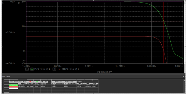
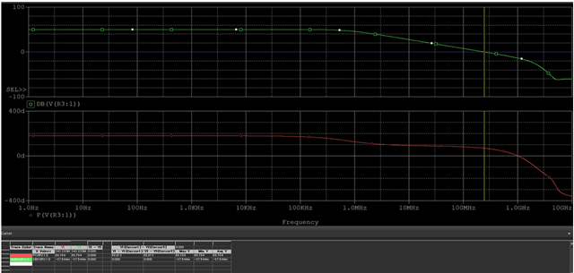
    Following simulation for Stability is correct? Phase margin is around 53.6 degree(-126.4) at around 0dB 


    Best Regards,

    ttd

  • Hi,

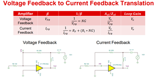
    The LMH6703 is also current feedback device, which would require the setup described in the video I referenced in the first post. As was previously stated, the model itself might not be modeling the open loop transimpedance gain of the device as well. The snippet below shows how to setup a voltage feedback amplifier and a current feedback amplifier. This snippet was from the current feedback amplifier series in the link shared above. It goes through one example using a different current feedback device that does model open loop transimpedance gain. 

    Best regards,

    Ignacio

  • Hi Ignacio,

    Thank you for your reply.

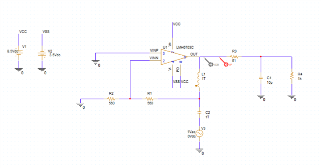
    I got approx. 68.8° Phase margin around 0dB at output with current feedback method(open loop) you suggested with PSpice for TI. 

    I believe the result is correct phase margin. 

     ■PSpice for TI

    Best Regards,

    ttd

  • Hi,

    I was able to get the same result in simulation. I would like to mention the 68 degrees seems higher than I would have guessed in this gain and Rf value as the datasheet shows a closed loop response with a little peaking. This is due to the model being overly optimistic and likely not capturing the real-life silicon perfectly.

    Best Regards,

    Ignacio