This thread has been locked.

If you have a related question, please click the "Ask a related question" button in the top right corner. The newly created question will be automatically linked to this question.

TLV3201: Datasheet suggest high frequency use, but practice is different

Part Number: TLV3201
Other Parts Discussed in Thread: TLV3231, LMV7219, TLV3601

Tool/software:

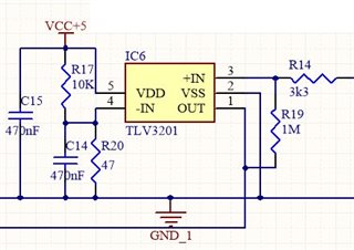
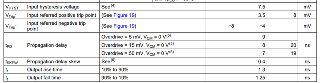
According to the datasheet is this a comparator with push/pull outputs.

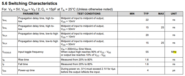
After see the datasheet it needs to be a very fast one.

I trusted the datasheet and implemented this in a design to make from a 20 millivolts sinus at 3MHz 0-5 Volt signal

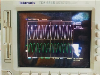
After getting the PCB and testing it, the disappointment was Hugh.

Checking threshold and input signals give that this TLV3201 must be able to work

Lowering the frequency to just under 1 MHz then it protested but i got a signal from 2.5 to 5 Volt

In the datasheet is nothing to find about maximum use full frequency.

Searching for a better one is the TLV 9022 but the packaging is different then the SOT23-5 from the TLV3201, and most of all I don't trust the datasheets anymore

I post this because I feel mislead.

  • Hi Ronald,

    I understand your frustration. Could you please provide me with the following information so that I could help debug your issue:

    1. Could you please provide me with the schematic of the circuit so that I can see how the TLV3201 is being used?

    2. Could you please provide oscilloscope waveforms of the testing you've done and what nodes you've probed?

    3. What are the input signals are you applying to the comparator and what output signals are you expecting?

    4. I'm not entirely sure how the TLV3201 is failing in your application. What does the output waveform look like when you are applying a 3MHz signal vs a 1MHz signal?

  • Hello Ronald R,

    Yes for push pull out, fast response.

    Is 20mV sine wave , Vrms, Vpeak, Vpp? Input overdrive timing specifications of 20mV imply that 20mV beyond Vos is immediately present. In a 20mV sine input, the voltage is gradually available and Vos can play a big role favoring one side.   

    Checking threshold and input signals give that this TLV3201 must be able to work

    Please provide wave forms of input and output. 

    In the datasheet is nothing to find about maximum use full frequency.

    Neither did I see a maximum frequency.

  • This simulation is used to test the 3201 in real life

    This is a picture from the simulation and made this on a breadboard

    this photo show the two input signals, the white line is the threshold signal, the signal from the white line to the top is 135mV, still no output from the comparator

    The actual information from both of the inputs, the white line is the threshold. The signal above the threshold is 135mV and still the comparator does not give any signal.

    The  maximum frequency which give a kind of square wave is 300 KHz with a signal from 2.5 to about 5V, with 1 resistor of 2k2 to ground and one from 2k2 to 5V.

  • Thank you for your reaction, I put some information as reply to Ron Michalick in where things become clear.

    In mean time I made two stage amplifier with the 2n3904 to reach my goal to get a square wave signal. 

  • I added this to show the values the scope give, threshold is 904mV, signal above the threshold is 244 mV with a output of 200mV to see in the second channel. I would expect a square wave from nearly 0 to nearly 5V

  • Ronald R.

    The output rise and fall times seem too slow. Can you estimate the capacitance on the output including board and scope probe. Capacitance can be an issue. Do you have a supply bypass capacitor close to the DUT. To drive output, there needs to be a short term power source near the DUT.

    Lastly, can you gate the input sine. Have it start and capture the first few pulses. Are the output pulses all the same?

  • Schematic placement

    PCB Placement

    The GND trace 0.6 mm wide and about 15mm long on a 0.8mm PCB the same is valid for the 5 Volt Supply with 22 uF 16Volt capacitor and terminated with C15 470nF

    I made all as short possible, the same I made on a breadboard and from that you see the earlier presented photos.

    On the breadboard I added a pre-amplifier with 1x 2n3904 to get more signal as seen on the oscilloscope pictures

    On the already made PCB it was not possible and used the 30 miliVolt as input signal with no output at all

    R16 is a 10 ohm resistor  as input impedance

  • Ronald R.

    It seems a device part number change is needed. One that is a pin to pin drop in. 

    There is the TLV3231 which is faster and maybe more importantly has a Fmax parameter, 55MHz with qualifiers for that spec.

    There is also (old school) very fast LMV7219, it has no F max and has significant IIB. The large hysteresis window may limiting.

    The TLV3601 is super fast, even higher IIB, far more than what you need. It does have a high Fmax spec.

    In summary, TLV3231 should be tried. For 50% duty cycle target the reference needs to match thew sine center voltage.

  • Thanks Ron Michallick,

    The proposed  TLV3231 is not available but the LMV7219 is already ordered. It seems again that is a fast comparator, nearly same as the TLV3201. I will keep you updated and after a few days will give you the result.

    With friendly regards,

    Ronald

  • Ronald R.

    One last question, was there more than one sample that exhibited the slow behavior. Other than a damaged comparator (or a lot of load capacitance) , I can't understand why the rise and fall were so slow. 

  • Ronald R.

    A colleague suggested that I ask more about the scope probe. Please see below.

    "Ask what scope probes were usied to measure. 1X? 10X? RG-58 direct connection? Did he calibrate the probes with the probe cal? Clip lead Gnd? Is he measuring directly at the output of the comparator. I used that TDS scope for years…and it can resolve ns risetimes easily *with* the correct, calibrated probes. Using the wrong 10x probes will severely distort the waveforms at high frequencies."

  • Hi Ron,

    I bought 10 pieces, still have a few, on the PCB as seen in previous picture, I got no out put, only when I put the TLV on wire pillars and used them on a breadboard I also got no signal poking around why not working and changing to a new part I got the same result. The only way I see on the scope a signal was when reducing the frequency to lower than 300KHz. The fact that the product was praised in heaven with the information on the datasheet made me very angry. Spend many hours and make costs to get a new design working.

    What bothered me the most is missing the maximum useful frequency on the datasheet.

  • I use many different probes depending on the unwanted signals I get when measuring, 2.6 MHz is not so high and easy to measure with my scope. I made a pre-amplifier with 2n3904 and could measure 5 millivolt  without any problem. 

    On the PCB I got no output signal but the input signal was clear and steady, the threshold voltage I measured with the scope, the datasheet give 1 millivolt is the input hysteresis, even with 100 millivolt no output signal

    The MLV is on the way and probably will receive it tomorrow, also a product without toggle frequency.

    I make the choice for the TLV after used a MCP6561 (toggle frequency 4 MHz) with the same outcome as the TLV, I thought the input current of 2 mA could be the problem. But the TLV proved that is not the case.

    The MLV I will try to make a final conclusion, but going to use a other design to solve this problem using discrete parts.

  • Hello Ron Michallick,

    As promised I returned with answers.

    1) All inputs need to be half the supply voltage, hysteresis can be made on this way too

    The way I tested the devices on a breadboard

    2) In general datasheets give offsets voltage on the input between 1mV and 10mV, same for the TLV3201. It suggests that switching from the output will happen if those voltages will exceed. Nothing is true about that, real life testing give that I need to supply 2.5Vtt sinus or Square wave signals to get a swinging output

    3) The datasheet also suggests that the switching can be done on very high speeds, I know this is relative but testing the MCP6561 who give in the datasheet 4 MHz toggle speed and compare to the TLV data give the idea that the TLV can do up to 10 MHZ or so. Nothing is true the MCP does in real live not more then 40 KHz and the TLV go to 300 KHz the MLV I have but not tested as I got very disappointed in the behave.

    General speaking I see datasheet changing to high level of scientific information with removing all normal graphs that are easy to interpret for stupid engineers like me, I spend hours to reveal the real useful information to be able doing my work. Also the "cheating" in datasheets and not mention the real useful limits is frustrating me. I get less and less trust in datasheets and also lost trust in the companies who making those electronic products. I have the idea that marketing is more important then give honest and true information. Hiding not relevant information behind scientific notations and overwhelm people with difficult things keep them away from reality. This strategy will finally become the bankruptcy from companies, as already noticed.

    I will close this thread and going todo my real work: designing of electronics. 

    Have a nice day