This thread has been locked.

If you have a related question, please click the "Ask a related question" button in the top right corner. The newly created question will be automatically linked to this question.

OPA192: stability using emitter follower

Part Number: OPA192
Other Parts Discussed in Thread: OPA2192, TINA-TI

Tool/software:

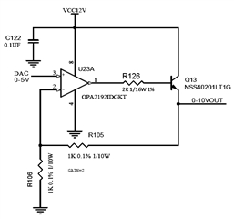
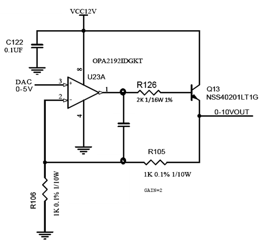
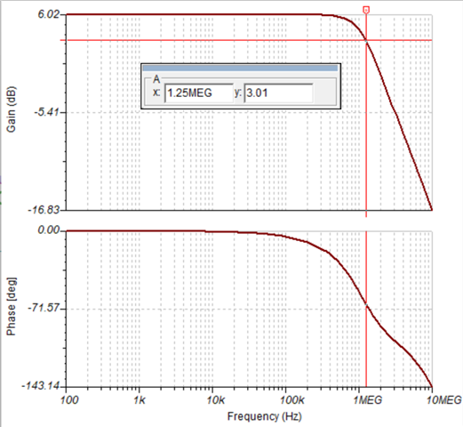
i am trying to determine if the OPA192 ckt below will be stable with an emitter follower and the base resistor inserted..

the application is used to drive a resistive load for up to 60ma. a base resistor is added for capacitive isolation but not sure this is sufficient.

i could not find the opamp in tina ti to model the ckt.

  • Hello Tom,

    R126 isolates capacitance from the output. However the feedback is subject to capacitance. 0-10V is likely to travel through a cable that has capacitance. 

    The extra capacitor (see below) can be added to support a wider range of capacitance. In case R105 feedback path has too much lag, the new cap can feedback a low phase loss feedback.

    Tina OPA2192 file can be downloaded here. https://www.ti.com/product/OPA192#design-tools-simulation

  • Hi Ron, thanks for the reply and info, especially on the cable capacitance.

    i was able to modify a Tina-TI reference model with the circuit i posted to run simulations. fyi, we have a proto board with this circuit so putting caps across the base and feedback resistors are easier to rework. modeling the cap as you marked up gave very good phase margin at around 680pf but started rolling off the output after 10hz.

    what i do not understand is how i can reliably determine with the simulation tool that i have good phase margin for stability. for example, placing a 0.1uf cap across the feedback resistor improves the phase margin (~60deg) yet the transient response shows severe oscillation. ive attached the Tina-TI files. please let me know if there is a setup in the tool i am not using correctly.

    OPA2192_ckt.zip

  • Tom,

    As changed this simulates with with max forward gain bandwidth without gain peaking. FYI: gain peaking suggest oscillation or high frequency ringing.

    OPA2192_ckt2.TSC

  • Hi Ron, thanks for shaing the file. this definitely seems to be te best compensation method, even with hi capacitance loads. 

    thanks for your help!