LM358: Analysis of large output deviation of LM358 circuit

Part Number: LM358

Tool/software:

The DC-IRIS aperture drive circuit on IPC uses LM358. Currently, the test department has found that the output deviation of some LM358 machines is much larger than that of normal machines. The phenomenon is described as follows, please send it to the technical support of suppliers for analysis and processing: The drive circuit and test points of the LM358 are shown below. A to O are voltage test points at different positions
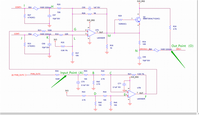
The point between C70 and R55 is used as the signal input point A, input different voltages between 0 and 3.3V, and the point between FB5 and R30 is the output measurement point O, which is used to measure the corresponding output voltages when different inputs are used. It is found that the normal chip and the deviated chip are placed on the same board (all other devices on the board are not moved, and all other devices on the board are not moved. Only replace different LM358). When the input voltage at point A is the same, the voltage deviation at output point O is very large, with a deviation of more than 1V. After many measurements, the deviation is basically stable. Take the voltage at input point A as 1.78V for example, the voltage at different points A to O of the normal chip and the chip with a large deviation is shown in the table:

In view of the above test situation, could you please help analyze the possible reasons and solutions for such a big difference between the input and output of U7A part?

  • Hi TI,

    We did ABA test and found that this deviation is affected by the LM358.

    Looking forward you reply.

    BR

    Cayden

  • Hi Cayden, 

    In view of the above test situation, could you please help analyze the possible reasons and solutions for such a big difference between the input and output of U7A part?
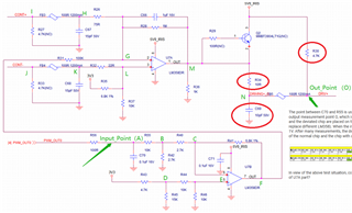
    Please check with the customer that the latest LM358's date code vs. previous batch (claimed to be normal operation). My guess is that the LM358 is using the latest batch. 

    https://www.mouser.com/PCN/Texas_Instruments_PCN20231219013_20231222114541159.pdf

    2nd, please check the following. The following 3 components' value in the circuit have not populated by mistakes, especially the values of 4.7kΩ and 10Ω.

    3rd - please let me know what is correct output voltage when PWM_OUT0 is present. What is the voltage signal at CONT+. 

    4th - Either op amp circuits are working properly. Yes, this is NOT a typo. We need to fix the issues for the customer. It is likely due to the latest revision of LM358 (this is my guess). 

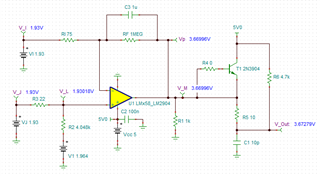
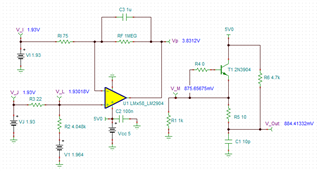
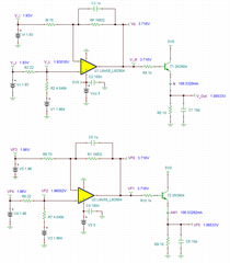
    This is how the circuit should work.


    And the V_OUT is determined by the voltage divider at  the output. My theory is that the old LM358 sinks less current than the current revision and thus the Vout was measured at approx. 0.81V. Q2 is never turned on and it is not doing anything. The Out_Point (DRV+) is basically determined by voltage divider. BTW, what is the load at DRV+ node. 

    LMx58_LM2904 DC-IRIS Control 12112024.TSC

    Is the customer located in Shenzhen? Write me via WebEx messaging. 

    Best,

    Raymond

  • Hi Herbert, 

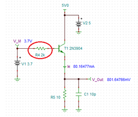
    There is a bug in output stage of DC-IRIS aperture driving circuit. I assume that the aperture control needs current to drive it, but I do not know what is the magnitude. Here is a quick fix for your application. 

    LMx58_LM2904 DC-IRIS Control Revision 12112024.TSC

    If you change the base resistor, see the marked red circle, it can control the output voltage in the last stage and output current. I realize that this is the existing design and I will do the minimum modification and meet your driving requirements. 

    If you have additional questions, please let me know. 

    Best,

    Raymond