This thread has been locked.
If you have a related question, please click the "Ask a related question" button in the top right corner. The newly created question will be automatically linked to this question.
Tool/software:
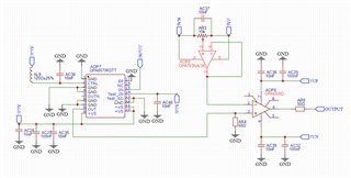
I am designing an amplifier to amplify the signal from a photomultiplier tube (PMT) and digitize the output using a standard digitizer.
I used a circuit incorporating the OPA857 and OPA693, but I am not getting any output signal. While adjusting the offset with the potentiometer, I can observe changes in the DC voltage level, but no signal is present.
I would greatly appreciate any assistance in identifying potential issues with the circuit or improving its design.
Hello Bhaskar,
Thank you for the information and debugging steps. I double-checked your connections, and they are correct. I have a few more quick questions:
Best Regards,
Sima
Thank you for the suggestions.
Hello Bhaskar,
Thank you for the update on each suggestion. I agree that 2. is the reason why you are not getting an output from the device with input current change. This device was designed to work from the internal reference voltage (1.83) and below. The output voltage range of the device is from 0.6V to 1.9V on a 3.3V single supply configuration. This 1.2-V swing corresponds to a maximum input current of 60 µA in the high-gain configuration, and 240 µA in the low-gain configuration when diode is sourcing current (cathode is biased to a positive voltage and anode is tied to the amplifier input). It forces the output to go low, below the device's internal reference (in other words, negative output when light falls on the PD).
Are you able to switch out PMT that works with positive high voltage supply? If not, are you able to switch out the amplifier with a non-integrated TIA since you are not using the OUTN functionality, such as OPA858 or OPA855?
Thank you,
Sima