This thread has been locked.

If you have a related question, please click the "Ask a related question" button in the top right corner. The newly created question will be automatically linked to this question.

OPA392: Limiting Total Noise

Part Number: OPA392
Other Parts Discussed in Thread: OPA310, OPA567, OPA569

Tool/software:

Hello,

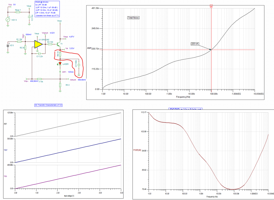
I'd like to pick up the referenced thread where it ended: Simulating the voltage-to-current converter circuit, we initially discussed (and simulated) the total noise up to 100 kHz. Then  pointed out that "total noise keeps increasing at higher frequency and thus the signal would have to be limited with LPF to get this value.". Now when I extended the simulation for total noise up to 10 MHz, that did not limit the total noise. It kept steeply increasing after 100 kHz.Marek explained this observation with "I believe that the increase in the total noise above 10MHz is caused by inaccurate modeling of the open-loop output impedance (Zo) and therefore is not real".

I understand that the model for a 13 MHz amplifier does not characterizes noise properly for frequencies above its gain bandwidth.

However, I'm interested about the noise between 100 kHz and 10 MHz that increases steeply. Is that real and if so why is it not limited by the LPF? Can it be limited further?

Thanks.

Best regards,
Dan

PS: if the referenced thread already provides the answer, please point me to it. I may have overlooked it.

  • Dan,

    I took a closer look at the cause of the increase in the current noise at higher frequency and it turns out it is actually related to the bias current thru T1 and not noise of OPA392.  Increasing the R5 to 40ohm lowers the laser current and noise bandwidth by 10x resulting in lowering of the total integrated current noise at 10Mhz from 560nA down to 79nA - see below.

  • Dear ,

    Thank you for replying to me.

    I understand that your circuit achieves lower total noise because you lowered load current from 125 mA down to 12.5 mA by increasing R5 from 4 to 40 Ohm. Of course this is not the operating point of the laser diode. What was your objective regarding this change? Did you do this to identify whether the OPA or the bias current are contributing to the total noise?

    Thanks. 
    Daniel

  • I understand that the laser diode operates at the higher bias current and the only reason to lower the operating point was to determine what controls the total current noise.  In the above case, it is not OPA392 but rather current level thru T1 that dominates the noise.  Of course, the actual simulated magnitude of the noise is only as good as the macro-models of the components used.

  • Thanks Marek for this clarification. 

    Sorry for not getting back to you earlier. I was evaluating different power supply designs for this voltage-to-current converter (aka current source) on the bench.

    Then I used the different power supplies designs and this current source circuit to drive a single mode laser diode:

    As you identified current through T1 as dominating noise source, I increased the LPF after transistor T1 (10 Ohm, 100 nF) which (according to the simulation) reduces the increase of Total Noise above 1 MHz that we had observed (in the simulation) without it.

    Regarding PSSR, I have to use a DCDC-converter. In order to reduce the noise from the buck converter, I added a PI filter and a low pass filter (Rsup=10 Ohm / Csup=100 uF, as you had suggested in the original thread)  and an LDO between Vcc and Vsup.

    I measured frequency stability of the laser diode and found that the results were an improvement over the existing current source. Further, the dominant "disturbance" was not the noise of the current source but the stability of the power supply. 

    Last question: As the current through T1 is the dominant noise source and as I only need to drive about 125 mA, could I get rid of the pass transistor T1 and drive the laser diode directly from an appropriate op amp in order to further improve noise levels?

    Thanks a lot for your support.
    Dan

  • Sorry Dan

    Marek was traveling last week and didn't get a chance to respond.  Sounds like you are wondering if one of our high output current amplifiers could be used.

    Looking at the OPA310 for example, that has 150mA output capability, I don't believe you will obtain your accuracy requirements due to voltage drop of the amplifier at a current level of 125mA.  Seems like your present solution is best option.  Regardless, Marek will chime in to give his input.

    Chuck

  • Hello , I appreciate your reassuring and encouraging comment. Thank you for responding while Marek is away. That is excellent customer care and one of the reasons I design with TI parts. The responses I receive from TI specialists in this forum are always helpful. I just wanted to share this.

  • Hi Daniel,

    Sorry for delay response. As far as your latest question goes regarding "the current through T1 as the dominant noise source and as I only need to drive about 125 mA, could I get rid of the pass transistor T1 and drive the laser diode directly from an appropriate op amp in order to further improve noise levels, " things are not as simple as they may appear. 

    1. For one, any op amp used to replace T1 will NOT be noise free and thus will also generate some noise, thus filtering will be needed

    2. 125mA output drive is a lot to ask for of most linear op amps - some like OPA310 may TYPICALLY source 150mA BUT the minimum output current is much less (see below) 

    The alterative would be to use parts like dual ALM2402F, or some of the costly power op amps like OPA567 or OPA569, but they will not be precision ones - see the entire list below:

     https://www.ti.com/amplifier-circuit/op-amps/power/products.html#1261max=5.5%3B24&451typ=0.2%3B10&sort=23typ;asc&