This thread has been locked.

If you have a related question, please click the "Ask a related question" button in the top right corner. The newly created question will be automatically linked to this question.

OPA2675: Tina TI Simulation

Part Number: OPA2675


Tool/software:

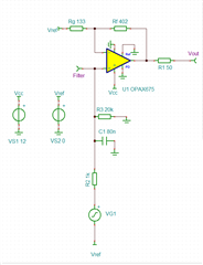
I am trying to simulate the said op amp in Tina TI with an RC filter and PWM. The results do not look consistent. At 100pct duty cycle (20KHz 3.3V) i get the required Vout but it takes 200 us to get anything above 1.1V. At 50pct duty cycle the Vout remains at 1.1V. From the graphs it seems that my RC filter works fine but the amplifier does not amplify the signal unless im at 100pct duty cycle. Is there anything wrong with my simulation?

  • Hi Anastasios,

    It seems like the signal is running into an input common-mode voltage limit which is why it seems to be clamping at 1.1V. If you change Vref to say 2.5V, do you see the signal you expect? I would also reduce the gain you are currently at as you would also be slamming at the output since the device can only swing ~10.9 with a supply of 12V.

    Best Regards,

    Ignacio