A related question is a question created from another question. When the related question is created, it will be automatically linked to the original question.
If you have a related question, please click the "Ask a related question" button in the top right corner. The newly created question will be automatically linked to this question.
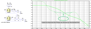
When using TLV9001 as a voltage follower as shown in the circuit diagram, is there a way to improve the frequency characteristics from 100Hz to 100kHz?
I implemented an RC filter to improve the noise level superimposed on the output voltage of the OPA397. Increasing the resistance improves the frequency characteristics, but it makes it impossible to meet the input voltage specifications of the downstream device.
Is there any solution other than changing the RC filter constant?
Does the noise originate from the input signal, or is it added by the opamp? In the first case, filter the input signal. In the second case, use a better opamp (which is not as cheap as an RC filter).
The TLV9001 and OPA397 are specified as having 30 and 6.5 nV/√Hz at 1 kHz and certain other test conditions. What are your actual requirements?
>Does the noise originate from the input signal, or is it added by the opamp? Noise signal appeared in the output signal.
>Please provide system requirements for the voltage follower The output voltage must be input to downstream devices, including the temperature characteristics of the op amp. Stable frequency characteristics are also required. In this circuit, the phase margin around 10 kHz must be improved to at least 60°.
If I continue to use this op-amp IC and RC filter, is it possible to improve the frequency characteristics by adding a circuit (such as a phase compensation circuit)?
Is this noise in the simulation or real world? What is the noise? Could it be an oscillation?
If the goal of the circuit was stated, we could help you better and much faster resolution. If I had to guess, it is a 0.5V reference buffer and I'd ask about the load current.
0.5V is input to the REF terminal of a current sense IC (INA296) that measures the current of a DC-DC converter switching at 100kHz. 100kHz noise components are superimposed on the output voltage of the voltage follower. I am worried that the around 100Khz phase margin is insufficient and it may oscillate.
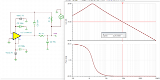
One option is to use a faster op amp like TLV9061 (10MHz) and remove the output load. Output impedance very low at low frequency; rising smoothly to just over 1 ohm at 100kHz.
You can keep TLV9001. 100k is now 0.16 Ohms. The phase shift in output Z is smooth suggesting good phase margin.
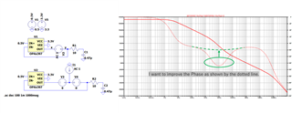
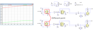
The solution you proposed was effective, but because wiring the board is difficult, I am thinking of taking the solution shown in the figure. In this circuit, when using TLV9002 and OPA397, why does the REF terminal voltage of the current SENSE IC (INA296) deviate by about 20mV? Also, are there any points to be careful of when using an op amp in this way?