This thread has been locked.

If you have a related question, please click the "Ask a related question" button in the top right corner. The newly created question will be automatically linked to this question.

TLV9304: The V+ !=V- of the TLV9304

Part Number: TLV9304
Other Parts Discussed in Thread: TLV9302,

Tool/software:

Dear MR/MS,   

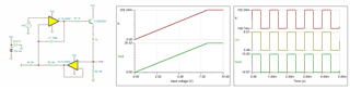
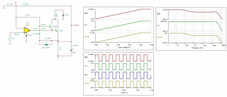
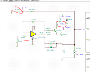
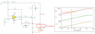
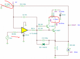
       We build a In-phase proportional amplifier with the TLV9302, the output of it connect to Base electrode of two BJT,  all of these components make a voltage source. And we use the Tina to simulate the circuit, the circuit is as below.  From the simulation results,  we can see that the resistance value of the output load can reach a minimum of 400omh(R23).

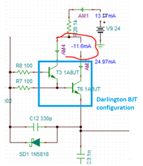
      But when the board in house, we test the actual circuit,  when the load is 979omh, the circuit can’t work well, the test data as below, we can see the error rate of the output voltages will be bigger when the input voltage to be smaller . And the Vbe, V+, V- listed as below. It seems like the positive and negative voltages of the operational amplifier are not equal, and the virtual break cannot be established when the circuit can’t work well. What causes the V+ to be not equal to V- of the TLV9304? Is it due to insufficient driving capability of the operational amplifier?

input voltage value (V)

Theoretical output voltage value (V)

The tested output voltage value(V)

Error rate

+' Input of TLV9304(V)

‘-' Input of TLV9304(V)

output of TLV9304(V)

Vb Of BJT(V)

Ve Of BJT(V)

Vc Of BJT(V)

Vbe(V)

4

10

10.052

0.52%

3.9621

3.9988

10.671

10.626

9.997

18.338

0.629

2.4

6

6.256

4.27%

2.377

2.3993

6.64

6.613

5.999

20.275

0.614

0.8

2

2.421

21.05%

0.7909

0.8597

2.653

2.5763

2.435

22.653

0.1413

0.2

0.5

0.384

23.20%

0.1962

0.1588

0.6137

0.7128

0.3809

23.73

0.3319

          When We change the resistance of the load R23, we found that when the resistance bigger than 30k, the circuit works well. The below data is recorded when load is 166k. Why is there is such a big gap between the results of the actual circuit and the simulation?  Is there something causing the operational amplifier to malfunction? Would u like to give us some suggestion? 

input voltage value (V)

Theoretical output voltage value (V)

The tested output voltage value(V)

Error rate

+' Input of TLV9304(V)

‘-' Input of TLV9304(V)

output of TLV9304(V)

Vb Of BJT(V)

Ve Of BJT(V)

Vc Of BJT(V)

Vbe

4

10

10.009

0.09%

3.962

4.0043

10.498

10.501

10.01

23.878

0.491

2.4

6

6.001

0.02%

2.3769

2.4009

6.49

6.495

6.002

23.899

0.493

0.8

2

1.997

0.15%

0.791

0.7988

2.4837

2.4896

1.997

23.919

0.4926

0.2

0.5

0.497

0.60%

0.1962

0.1987

0.9527

0.9529

0.4967

23.927

0.4562

             simulation.docx

  • Hi Liz,

    What causes the V+ to be not equal to V- of the TLV9304? Is it due to insufficient driving capability of the operational amplifier?

    The circuit looks like V-I converter. The root cause is that the TLV9304 is not operating in linear mode. It is design issues. Please provide me the design requirements and I can fix it for you. 

    My guess is that this is what you have in mind. Here is my simulation as an example.  

    TLV9304 V-I 03122025.TSC

    Here is the higher constant current settings. 

    If you have other questions, please let me know. 

    Best,

    Raymond

  • voltage source - AMC1351 - test.TSC

    Hi Raymond,

             The attached file is my circuit. My original requirement is to get a voltage source, input 0~4V, output 0~10V. I add the BJT to improve the drive capability, due to the load(R23) is in the far end. Seried a 1k resistor between the BJT (collector)and the 24V power supply is to prevent the load short from causing circuit burnout.

            Could we make some minor modifications to our circuit to ensure that the operational amplifier operates in the linear region? Would u like to give me suggestion? Thanks.

  • Hi Liz,

    I modified your circuit and its linear range at input is from 0V to approx. 4.2V range, and output is up to 10.38V range. The circuit's current is limited by the 1kohm resistors. The useful BW of the circuit, and it has approx. 106Hz range. 

    voltage source - AMC1351 - modified.TSC

    To simplify it further, I think that you only need to one BJT, since it does not draw significant amount of current. 

    In theory, TLV9302 is capable to source the amount of current (<25mA) over temperature. So this is up to you. 

    If you have other questions, please let me know. 

    Best,

    Raymond

  • Hi Raymond,

               Our output is DC signal, I think the BW of the circuit is ok. But I moved the two 1k current limited resistors as mentioned by your reply, the circuit did not work well either. 

               Until we moved the R6, R27 and R28( As the my attached file), and the circuit seems to work well when the R23 bigger than 500omh, the below data is recorded when R23=979omh. But however, as the simulation of the tina as attached before, if we moved R6, R27 and R28, the resistance of R23 can be as small as 10omh. Why is there is such a big gap between the results of the actual circuit and the simulation?  

    input voltage value (V)

    Theoretical output voltage value (V)

    The tested output voltage value(V)

    Error rate

    +' Input of TLV9304(V)

    ‘-' Input of TLV9304(V)

    output of TLV9304(V)

    Vb Of BJT(V)

    Ve Of BJT(V)

    Vc Of BJT(V)

    VBE

    4

    10

    10.004

    0.04%

    3.9954

    3.9991

    10.63

    10.627

    10.035

    23.995

    0.592

    2.4

    6

    6.003

    0.05%

    2.3972

    2.3995

    6.602

    6.601

    6.021

    24.006

    0.58

    0.8

    2

    2.0037

    0.18%

    0.7982

    0.7994

    2.5603

    2.5602

    2.0098

    24.018

    0.5504

    0.2

    0.5

    0.5163

    3.26%

    0.1986

    0.2047

    1.0208

    1.0208

    0.5174

    24.021

    0.5034

     Thanks,

    Liz

  • Hi Raymond,

           I found the current of the given circuit was strange, the marking current is negative.  And why the R9 is 60k? 


  • Hi Liz,

       I found the current of the given circuit was strange, the marking current is negative.  And why the R9 is 60k? 

    R9 is determined to match the op amp's input impedance, which is 100kohm||150kohm. 

    This is V-to-I converter, and the circuit is only souring the positive current from the driver. Where is negative current from?

    Why is there is such a big gap between the results of the actual circuit and the simulation?  

    It is good that you provide me with these test measurement, but this is the V-I circuit and I need to know the output current information. 

    What tolerances of resistors are you using. For instance, VSOUT = 10.63Vdc, if the R23 or Rsense = 400 ohm, then the current is 10.63V/400 = 26.575mA. 

    I need to have the 400 ohm resistor information and what is the max. constant current you want to get out of the circuit.   

    The circuit looks like a Darlington configuration to boost the BJT's collector's current, but it is not configurated properly. In addition, 1kohm may limit the BJT's collector current, depending on the V-I design intent. 

    Please provide me the V-I design requirements for the circuit. 

    Best,

    Raymond

  • Hi Raymond,

             The tolerances of resistors are 0.1%. The max load current is 10mA. And the output will to drive the far end device. Our original purpose of adding  the 1k resistor was to prevent external short circuit faults.

    Thanks,

    Liz

  • Hi Liz, 

    Is there a question in your latest response? Yes, the circuit is able to drive 10mA in constant current. Based on your information, the NPN is dissipate approx. 100mW of power in DC --> 24V - 10mA*1kΩ - 0.1mA*400 = 10V across the collect and emitter, and 10V*10mA is the power dissipation. Yes, 1kΩ resistor is able to protect the NPN if the circuit is shorted. 

    You may use two NPNs to help the share the output current, but the following NPNs are Darlington configurations and one is still taken the most of current load in the circuit. If you want to share the output current via PNPs, you need to place them in parallel. 

    If you have other questions, please let me know. 

    Best,

    Raymond