This thread has been locked.

If you have a related question, please click the "Ask a related question" button in the top right corner. The newly created question will be automatically linked to this question.

VCA824: Too much offset in output of single-ended amp

Part Number: VCA824

Tool/software:

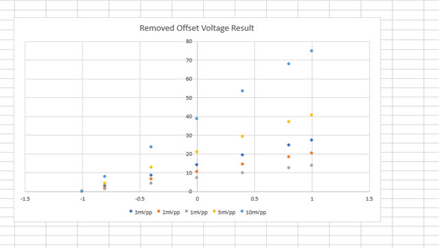
Simulation (in LTSpice, sorry) of my VCA824-based circuit showed DC offset that increases with gain. I think that's the model trying to represent the input offset chip-chip variation. I thought I could live with the worst case offset, but it turned out to be so much worse when I breadboarded the circuit. Unless I can remove the offset somehow, I can't use this circuit.

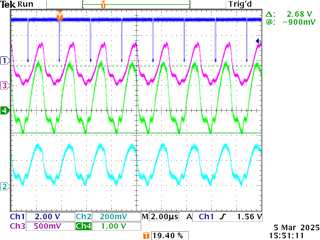
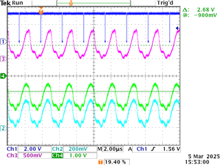
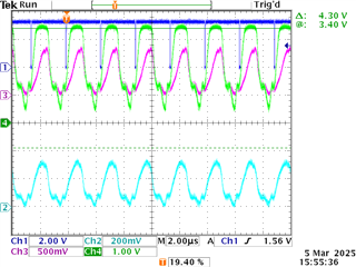
examples attached. In these, the input to the VCA824 is the cyan trace, and the output is the green trace.

Vg = 115 mV results in this:

Vg = -0.512V

Vg = 0.512V

I'm attaching a JPG of the circuit; I can provide the LTSPICE model if that would help, but I think this is more an application question than a simulation question. QUESTION: is there any way to remove the offset from the VCA824? The input to the VCA 824 is single-ended and will always be >0V

  • Hello Michael,

      Thank you for the detailed explanation! Quick question on one point: when you mentioned DC offset that increases with gain, are you seeing DC offset changes with varying gain control? If you are measuring offset voltage at the output of the VCA824, this will change with gain due to being gained up depending on VG set.

      I recently looked into VCA824 output voltage vs Vg. I was able to measure offset voltage by measuring the output vs Vg at 0V input voltage. With this data, I removed this value to any of the other input voltages vs Vg. Below is data I took in the lab at DC input voltages. 

    Best Regards,

    Sima 

  • Hello Michael , 

    On top of Sima question above , we are developing a new VGA which will sample in Mid 2025 which has a pin to calibrate and make the offset 0. Can we have a quick call with you to understand the issue you are facing and try to fix the issue if not in VCA824 but with the new part.

  • Most emphatically YES, I am seeing increased offset with addition of gain. The green trace in the scope shots I included is the output of the VCA824 at three different values of Vg. Input is the same (cyan trace) in all three.

  • Hello Michael,

      Would you be able to change out R10 to 402 and R4 to 80 for debugging purposes. High resistor values could cause instability, but not sure if yours is high enough to be causing this issue. It is good to rule that out first.

      Also, is the input (cyan trace) at 0V DC? And, would you be able to tell me what the DC values are for the output (green) at each of those gain points. 

    Thank you,
    Sima

  • Hi Sima

    2nd question first: input is near 0V - there might be a small offset. DC values can be determined from the cursor values ...oh wait, no it can't, I failed to adjust the cursors, sorry. Top trace offset is ~-900mV, middle trace offset is ~-2.0V, lowest trace offset is ~+80mV.

    I made the resistor changes you suggested. Offset improved a great deal, but still varies about 100mV over the Vg range ~ -0.5V to +0.5V, and now gets more negative as Vg becomes more positive. It's still too much offset, ranging from .230 mV to -340 mV.