Tool/software:
Hi, TI's Masters:
I'm trying to test input current of OPA2188, the test topology is shown below:

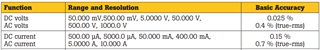
I use a portal multi-meter like FLUKE 289C to measure the voltages of A and B point, then divide the value by 10K, then get the input current of OPA2188.
but here comes a strange phenomenon:
case 1: the black probe contact BAT-, and red probe to A and B respectively, then change the input voltage from 100V to 800V, 100V step, the measure data is as followed below:
| input voltage/V | voltage A/V | voltage B/V |
| 100 | 0.2005 | 0.2005 |
| 200 | 0.3871 | 0.3868 |
| 300 | 0.5737 | 0.5732 |
| 400 | 0.7604 | 0.7597 |
| 500 | 0.9476 | 0.9468 |
| 600 | 1.1342 | 1.1331 |
| 700 | 1.3215 | 1.3203 |
| 800 | 1.5090 | 1.5075 |
I don't understand why the voltage difference between A and B become more and more with input voltage rising.
and the V(A-B)=1.5mV at 800V input, so the current across 10K is nearly 150nA, which is ten times more than datasheet.
case 2: I tried to measure A and B immediately, black probe to A and red probe to B, this time the V(A-B) is always nearly 10uV regardless of Vin, less than case 1 much a lot.
So which case is the correct measurement method? and why?
thanks a lot!