A related question is a question created from another question. When the related question is created, it will be automatically linked to the original question.
If you have a related question, please click the "Ask a related question" button in the top right corner. The newly created question will be automatically linked to this question.
Yes, these are both low-voltage instrumentation amplifiers, however they have very different architectures. Be mindful of the differences when you are making the substitution.
Before using the INA333 in place of the INA326, know that while the pinout is the same, there are some implementation differences. You must connect a resistor to the "R2/Ref" pin for 326. Additionally the two devices will have different valid common-modes.
Check the valid common-mode range for your application using the analog engineers calculator. If you have ensured you are in an acceptable output range based on your input voltages, then you may use the INA333 instead of the INA326.
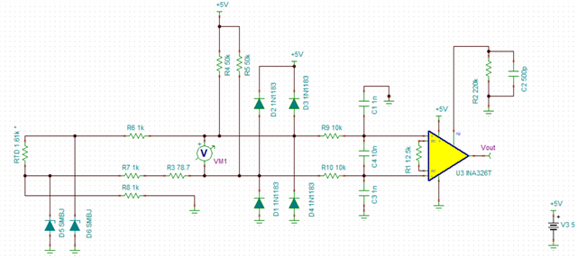
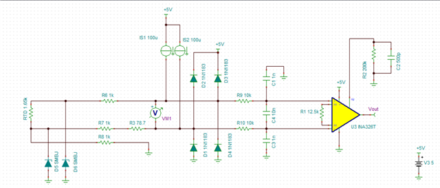
Thank you for providing the screen captures of the simulations.
I noticed for INA326 simulation, you have a * on your RTD, what is the range of values on the RTD? Could you please provide your .tsc? What type of sweep is being performed? DC, AC, transient?
Thank you for the additional information, .tsc stands for the TINA file. I built a version on my end & received weird results, see attached: 3326.rtd.TSC
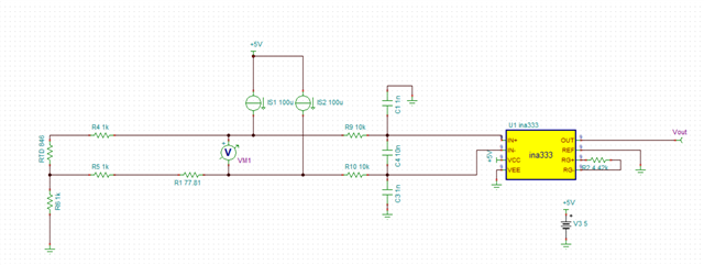
If we consider the input from the RTD:
RTD Range (Ω)
846
1770
VM1
76.8m
169.22m
VIN+
384m
477m
VIN-
307m
307m
VCM
345.6m
391.61m
Vdiff
±38.4m
±84.61m
Vout ideal (G=23)
±883.2m
±1.946V
RTD range 846 to 1770 ohms, results in VCM range of 345.6mV to 391.61mV with Vdiff of ±38.4mV to ±84.61mV.
Considering the power supply in both of the schematics above, this will not work as the amplifiers cannot output below the negative rail. What power supplies do you have in your system?
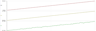
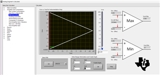
Please see the VCM vs VOUT plot for the INA333 with the configuration you have provided.
With a 5V, single supply, gain of 23, and a common-mode voltage of ~350mV to ~390mV, your valid output range will not exceed 600mV. Your max input voltage differential that can linearly be output is 25.3mV.
Generally the input common-mode range should be above the V- rail to avoid saturating the internal nodes of the instrumentation amplifier.
I'm not sure that the INA333 is a good fit for this application. You may want to look into a 2-amp INA with VCM near V-, like the INA122. Please note that the VCM vs VOUT plot in the analog engineer's calculator tool is incorrect for the INA122.