This thread has been locked.

If you have a related question, please click the "Ask a related question" button in the top right corner. The newly created question will be automatically linked to this question.

THS4551: How to calculate the cutoff frequency of an MFB circuit in a differential topology?

Part Number: THS4551

Tool/software:

The calculation for a single-ended MFB circuit can be referenced via this link:    sim.okawa-denshi.jp/.../Fkeisan.htm

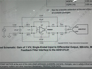
However, for a differential MFB circuit like the picture shown below, how should the cutoff frequency be calculated? Could you provide the calculation formula?

Also, how can simulation be used to quickly verify whether the calculation is correct?​

  • Hello Chao,

    I can support this request for you.  For balanced (or differential) filters the math is mostly the same.  The difference between single-ended and differential filters is with the passive components which have ground (GND) nets in the calculator tool for single-ended.

    For the 470pF capacitor in the THS4551 example in your reply, this capacitor is 1/2 of the value calculated by the single-ended design (940pF).  This is because two equal-value capacitors in series are equivalent to one capacitor with half the value (like parallel resistors).  

    The value for Cf (270pF), Rf (1.2kOhm) and Rg (1.2kOhm) remain the same for single-ended or differential.  You need only replicate the feedback and gain resistors for the other side of the FDA.  The 330 Ohm input resistor also keeps the same value; this resistor is R2 in your shared example website calculator.

     I hope this helps.  Please let me know if you have additional questions.

    Best,

    Alec

  • Hi  Alec

          Thank you for solving my confusion! I have another question: how does the 1nF capacitor in the example affect the cutoff frequency? Can it be treated as an RC filter circuit composed of a 330Ω resistor and a 2nF capacitor when calculating the cutoff frequency?

    Thanks!

    Chao Shen

  • Hello Chao,

    The 1nF capacitor in parallel at the two input nodes is not for the active filter.  This capacitor is often drawn or shown in EVMs or datasheets, but can be left DNP (do not populate) for most designs.  This input capacitor helps provide additional stability if the FDA circuit needs to compensate for instability caused by the feedback network or load.

    For the design we are discussing, this 1nF capacitor would be considered an 'extra feature' that would only be used (put onto the board) if needed.  Many EVM boards or designs will either not place this capacitor (DNP or leave unsoldered) or remove it from the design.

    Your MFB filter consideration is okay with only Rg, Rf, Rinput, Cinput, Cf as we discussed above.

    I am happy to help and answer your questions.  

    I am overall working on writing some content for differential amplifier (FDA) filter design; I appreciate your good questions.

    Thank you!

    Best,

    Alec

  • Hi  Alec

        Understood, now I have a clearer understanding of MFB circuits. Thank you for your help.

    Thanks!

    Chao Shen


  • Hello Chao,

    Absolutely, thank you for the good question!  

    Best,

    Alec