This thread has been locked.

If you have a related question, please click the "Ask a related question" button in the top right corner. The newly created question will be automatically linked to this question.

OPA827: 0.1Hz to 10Hz Noise Filter Project

Part Number: OPA827

Tool/software:

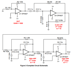
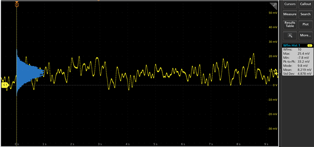
I am looking to test a voltage reference with low noise under 10uVRMS with the Noise filter made in the SLAU522 project. I have made the measurement for the regulator on the test fixture. It looks like my data matches what was collected in the paper. I am mostly looking to have a meeting with an engineer discussing the findings they may have had, as well as compare some data I have collected with a remake of this project. 

  • Hi Tristan, 

    You are referring to the following circuit. I was not involved in the measurement, but Art is the author. Art is OoO currently. If you have specific questions, I may be able to help. Otherwise, you may have to wait.  

    https://www.ti.com/lit/ug/slau522/slau522.pdf?ts=1749200937971

    Please let me know. 

    Best,

    Raymond

  • Hello Raymond, I am looking to re-orient this bandpass to a 0.1Hz to 200kHz filter with the same OP-amps. 

    I have made a measurement with the 0.1Hz to 10Hz outside of a faraday and I usually get around 270nVp-p to 300nVp-p. I expect the AC line Noise, or other external noise to be the reason for this higher measurement. However, the values I am looking for are higher RMS wise. Should I assume that this amount of extra noise is nothing since the amounts I am looking for would be almost more than 40uVp-p in this frequency range? 

    Here is an example of a quick measurement I made with 50Ω to gnd on the input. 

    Also, with the filter being changed to 200kHz bandwidth I know the noise can be around 160uVRMS just from the DUT to be measured with the BNC in. What would be a good gain amount to change the Op-amps to since it would be on the order of 10vRMS with the 100k gain? I know this originally was set-up to make sure the bandpass gain did not add to the noise measured, but our numbers will be much larger than the 270nVp-p that the op amp produces, as well as the extra uVRMS noise added from passive components in the filters.

  • Tristan,

    1. You are correct that the discrepancy in your noise readings may be due to noise pickup.  However, since the circuit limits the bandwidth to 10Hz with a 4th order LPF it is unlikely to be 50Hz or 60Hz power line noise.  In general, errors you see in this measurement are from temperature drift of the device.  Typically the measurement is made across 10 seconds and ambient temperature variation can be enough to cause the peak-to-peak measurement to be larger than expected.  When testing very low noise devices for low frequency noise, sometimes I used a controlled temperature environment.  I also use a shielded (steel) enclosure.  Note that I use steebecause it has good low frequency shielding benefits (see Henry Ott literature).  You may want to look at your measurement on a spectrum analyzer to see if the noise spectrum matches what you expect.  Extrinsic noise will show up at a specific frequency whereas intrinsic noise will show up as 1/f and broadband.
    2. You can change the filter to 200kHz using Filter pro .  You don't really need such an elaborate filter for the wide bandwidth noise test.  A simple 1st order 200kHz low pass RC filter is normally sufficient.
    3. If your total noise is 160uV RMS, that means the peak-to-peak is about 6*160uV = 960uVpp.  If you are trying to measure noise on an oscilloscope 960uVpp is a little low for a good reading.  I would gain this up by a factor of 10x or 100x.  The minimum resolution for most scopes ranges from 1mV/div to 10mV/div.  You want to make sure you can get a few divisions for your noise reading.  960uVpp is about 1mV, so in a gain of 10x you would get 10mVpp and you should be able to get a good reading on the scope. 

    I hope this helps.  Let me know if you have further questions.

    Best regards, Art