This thread has been locked.

If you have a related question, please click the "Ask a related question" button in the top right corner. The newly created question will be automatically linked to this question.

LMC7101: LMC7101AIM5

Part Number: LMC7101

Tool/software:

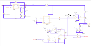
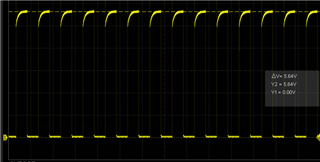
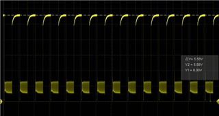
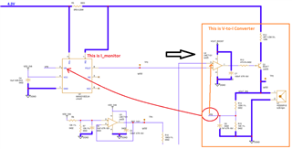
I have a problem with this amplifier in my circuit because in some cases it does not work correctly and I see the disturbed signal as in the attached figure. It is used as a comparator and at the amplifier input I have an alternating square wave signal from 0V to 0.4V on both inputs. Then by raising the output resistance of the amplifier and leaving it floating, on the one that does not give me the disturbance the output is low at 0V while in those where it gives me the disturbance it is fixed high and always remains so even leaving it on a working board. I then tried to mount the amplifier alone on a breadboard. I connected the two inputs together to ground, the power supply to 7.3V with a 100nF capacitor to ground and I connected the output with a 1k load resistor. Even in this condition on some I have the output that goes high, and therefore once mounted on my device it gives me the disturbance, while in other houses it is low as I expect it to be. Can you tell me what could be causing the problem? I don't know if maybe having the two inputs on the same level can cause this problem. In that case, can you also provide me with an alternative to this component that can be used as a comparator and that is pin to pin with a max VCC of at least 8v. thanks
  • Hi Matteo, 

    I have an alternating square wave signal from 0V to 0.4V on both inputs.

    Here may be the issues. The box in orange is V-to-I converter and Vfb node follows the LMC7101's pin3 at the input. MAX4210 is a current monitor, where you feed your Vfb to the input of the current monitor. I do not think that you can establish a transfer function between Vfb and Vout at MAX4210 current monitor. 

    The current monitor and V-to-I converter are two separate circuits, and current at Vfb is generated due to the controlled current*R15, so I am not clear what you are trying to do. 

    The circuit inside of orange box is a low side V-to-I converter (NPN). There is also a version to do the same V-to-I conversion on the high side with PNP transistor. So I need to understand what current level do you want to control. 

    FYI, I am unable to support you with competitors' product. So if you want to have the support, you have to use all TI product. Otherwise, I won't be able to support in details. 

    Best,

    Raymond

  • but my main question was: why if I connect the amplifier alone on a board and put the inputs in common to gnd and an RL of 1k on the output why on some I see the output high at VCC and on others it is low at 0v? Is this due to the fact that I have the same voltage value on the two inputs and can it damage the component?
    
    
  • Hi Matteo, 

    why if I connect the amplifier alone on a board and put the inputs in common to gnd and an RL of 1k on the output why on some I see the output high at VCC and on others it is low at 0v? Is this due to the fact that I have the same voltage value on the two inputs and can it damage the component?

    I am not sure that LMC7101 in V-to-I converter is operating in a linear mode. If the negative feedback is incomplete or not operating in a linear mode, the circuit may be operating in a comparator mode. Maybe this is why you see Vcc or GND  potential at the op amp's output. If Vin+ is not close to Vin- at the LMC7101 in a closed loop, the configuration is not operating in a linear mode. 

    If you have other questions, please let me know. 

    Best,

    Raymond