This thread has been locked.

If you have a related question, please click the "Ask a related question" button in the top right corner. The newly created question will be automatically linked to this question.

OPA4180: output swing and power sequence problem

Part Number: OPA4180
Other Parts Discussed in Thread: OPA177, OPA4205, OPA4277, OPA4206, OPA4202, INA188, OPA202

Tool/software:

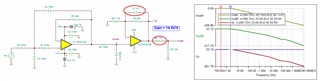
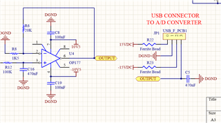
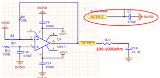
I am using an analog amplifier circuit using OP177GPZ for more than 15 years. Recently I have switch to OPA4180 instead of OP177. But I face two different problem. Circuit schematic is same except OP177 and OPA4180.

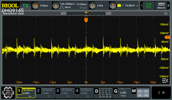
1-) Output swings compared to OP177 when I test same loadcell and setup board with OPA4180. I have a test setup that I test my boards. On my test setup this swing is not that noticeable. But when I connect my board to the machine this swing becomes noticeable. Only difference between test setup and machine is cable lengths I think. output of OPA4180 is connected to PLC module. In test setup cable length is shorter. both from loadcell to amplifier board and from amplifier board to PLC module. Swing has very slow frequency. approximately 1-2 minutes. And voltage change approximately 2-3mV peak to peak.

2-) Depend on how power connector is plugged on the board output of OPA4180 changes. My power connector has +15v, -15V, GND and analog output pins. It is a 3.5mm pluggable pcb terminal. While plugging the connector if +15V rail and -15V rail makes contact in different order output becomes maximum possible positive output. no matter I apply signal on input of opa4180 output does not change. when I re-plug connector then it starts to operate correctly. 


Does anyone has an idea about these observations.

Thanks.

  • Hi Dogan,

    Could you show me your schematic? If you do not want to post over the E2E in open forum, you may send a "friendship" request and send me the schematic when the E2E private communication is established. 

    OPA177 is capable to source more current than OPA4180, but I suspected that this may not be the issue, unless the OPA4180 is unable to support the load current per the driving conditions. 

    It is likely that your cable length has issues. The longer cable length as high parasitic capacitance associated with the test setup, and it may result in op amp oscillation or poor stability.  You may consider to place 100Ω resistor between the op amp's output and cable connector; and this may solve some of your issues. But it will be the best to take a closer look at the loop stability. Please calculate the parasitic capacitance of your cable and let me know. 

    While plugging the connector if +15V rail and -15V rail makes contact in different order output becomes maximum possible positive output. no matter I apply signal on input of opa4180 output does not change. when I re-plug connector then it starts to operate correctly. 

    It sounds like that OPA4180 reached a saturation at output somehow;  and it is working after the system is power cycled. 

    If you have other questions, please let me know. 

    Best,

    Raymond

  • X_OLCC_1V1.pdfX_OLCB_1V0.pdf

    Dear Raymond,

    I have put 2 schematics. some parts are not populated like ADR435, AD5611, AD7391. On both boards I am adjusting reference pin on ad620 with a POT R9 and R16 on different boards. 

    How can I measure parasitic capacitance of my cable. This is not the first time I am using OPA4180 on a machine. Until now I have used 150 boards with OPA4180. In different machines of course. Some have similar cable lengths some shorter. I have not experience this much of ripple on output in any other machine before but some how from the first board until now I was not happy about OPA4180 because even it is very hard to detect difference because of low voltage levels I was noticing weird oscillation with very low frequency like couple of minutes. But oscilations were reasonable on test setup or on some boards nothing weird happens. And there not much a ripple on the output. On this machine output has huge ripples and it swings. I am going to test different cable lengths and board to further investigate the root of the problem.

    Is 100 ohm effect drift characteristic of the board. Do I need to use low temp coefficient resistor on this.

    Abour power sequence what can I do about it? Why OP177 does not have such a problem but OPA4180 has. While I am testing boards I noticed this. normally you do not plug and un plug boards on the machine. But I suspect that in regular operation without touching connector. Can output saturate or not when the power is switched on.This is nightmare for me.

  • Hi Dogan, 

    How can I measure parasitic capacitance of my cable

    You can use LCR meter to measure the parasitic capacitance of you cable. Typically, a quality audio cable will specify the pF/foot and indicate the parasitic capacitance in their product. 

    Abour power sequence what can I do about it? Why OP177 does not have such a problem but OPA4180 has.

    The issues you encountered are op amp loop stability issues, where different op amp needs to compensate the Rload and Cload differently depending on the op amp's characteristics, such as open loop output impedance, op amp's BW and phase margin etc.. Here is some information about the loop stability issues in op amps. 

    https://www.ti.com/video/series/precision-labs/ti-precision-labs-op-amps.html

    Per your schematic, here is the output characteristics. If I understand your issues, please modify the OUTB stages as shown below. You may not need to measure the cable's parasitic capacitance. The modification should be able to drive output capacitance up to 10nF. 

    OPA4180 Sallenkey Filter 06162025.TSC

    Generally, chopper is not the best op amp to configure for active filter. It may be ok for your case, since the BW is so low, but I would try to lower the input impedance and increase the capacitive value for the Sallenkey filter. 

    https://www.ti.com/lit/wp/sboa586a/sboa586a.pdf?ts=1750035181225

    If you have other questions, please let me know. 

    Best,

    Raymond


  • Hi Dogan, 

    I am going to close this query, since I have not heard from you. 

    If you have additional questions, please let us know. 

    Best,

    Raymond

  • Dear Raymond,

    I have made some measurements. When I measure capacitance between output cable between OPA4180 output and PLC input it says that 1.7nF. When power off and OPA4180 is removed from the system. Just cables.

    When I measure same capacitance at my test workbench. It is same like 1.7nF

    But boards behave differently at test workbench.

    I did put 1nF and 75R at the output and fast oscillations mostly gone. So we have made some progress. But some boards still suffer slow frequency swings.

    When I enter on cross reference dialog on texas OP177. I have some IC's recomended.

    One of them is OPA4277 ( 4 opamp version ) and it says OPA4205 is newer alternative.And also OPA4206. 

    They are mostly pin to pin identical with OPA4180.

    Do you think checking those will help?

  • For more than 10 years I have been using OP177 with following schematic at the output.

    This C5 capacitor is 470nF. Once I switch from OP177 to OPA4180 I have noticed the oscillations. And previously I was offered to remove C5. Which it solved the issue back then. But it was on my test setup.

    do you think transition from DIP to SMD packages have some effect? OP177 that I use was dip package.

  • Hi Dogan, 

    When I measure same capacitance at my test workbench. It is same like 1.7nF

    A typical quality coaxial cable has parasitic capacitance around 25-35pF/foot, poor quality coaxial cable could go up to 100pF/foot range or higher. 1.7nF parasitic capacitive load at an op amp's output can cause an op amp to be destabilized. Typically, you need to place a  50-100ohm resistor at the output of the op amp to "isolate" the direct parasitic capacitive load and improve the phase margin of the op amp. This is related to op amp's stability issues when driving a load. 

    This C5 capacitor is 470nF. Once I switch from OP177 to OPA4180 I have noticed the oscillations. And previously I was offered to remove C5. Which it solved the issue back then. But it was on my test setup.

    No op amp is able to drive large capacitive load direction. 470nF is a large capacitive load;  OPA177 is unable to drive it directly. It is possible that you did not observe the oscillation while using OPA177, but OPA4180 did. An op amp is required to be compensated if it is driving a large capacitive load,. Please let me know which op amp you are going to use and I will performance loop stability analysis and try to compensate an op amp and improve its phase margin.   

    Best.

    Raymond

  • Dear Raymond,

    I am talking about OP177 from analog devices not OPA177 from texas. I have been using OP177 for more than 10 years without any oscillation or swing problem. I have spent hundreds of hours on checking output waveform of OP177 with scope. Believe me, there may be an oscillation but for me it is not detectable. when I generally test output waveform of the OP177 I switch to ac on scope so that I can set voltage divisions low. 

    On 2023 when I first test OP4180 on this forum it is suggested to remove 470nf. Right now we are still producing OP177 boards. and 470nF is still populated on boards. On OPA4180 boards on second version I completely remove 470nF and on test bench I did not see any oscillations but I did not check it with scope. I will check this with scope too.

    OP177 DIP package is quite expensive and I need to use 3 op amps in my board. My alternatives

    1-) Going back to OP177. ( I have already designed and manufacture small amount of boards with OP177 for just in case I face problem, now maybe it is time to use that design )

    2-) Going back OP177 with SMD package. SMD version is cheaper but I need to redesign and manufacture board.

    3-) Fixing issues with OPA4180. I have 300 OPA4180 in my stock and I like to use them. but it seems that I need to modify my board.

    4-) Switching to a standard op amp like OPA4206. I need to buy new components and 300 OPA4180 will go to dustbin.

  • Hi Dogan, 

    I see that you are referring to  OP177GPZ.  OP177GPZ's p2p compatible op amp is shown below. 

    https://www.ti.com/cross-reference-search/singlepart?searchTerm=OP177GPZ

    1-) Going back to OP177. ( I have already designed and manufacture small amount of boards with OP177 for just in case I face problem, now maybe it is time to use that design )

    You may use one of the p2p part to replace OP177 op amps. 

    2-) Going back OP177 with SMD package. SMD version is cheaper but I need to redesign and manufacture board.

    You can use SMD to DIP breakout board to check out the performance first. You can get these from digikey, mouser or even ebay.com

    3-) Fixing issues with OPA4180. I have 300 OPA4180 in my stock and I like to use them. but it seems that I need to modify my board.

    Please let me know what is the max. capacitive load that you want to drive and I can compensate the op amp circuit for you. 

    4-) Switching to a standard op amp like OPA4206. I need to buy new components and 300 OPA4180 will go to dustbin.

    You can buy directly from TI E-store. Please provide me the schematic and I can simulate and check it out for you. 

    https://www.ti.com/product/OPA4206?login-check=true#order-quality

    If you have other questions, please let me know. 

    Best,

    Raymond

  • Dear Raymond,

    I have measured capacitance of input pin of analog input module. It says 1.5nF. When I connect cable it goes to 1.7nF. We can go for 10nF for maximum capacitance that we can have on different type of machines.

    I will get a scope and show you the output of op177 and opa4180. Also I can buy OPA177 and check whether there is a difference between OP177.

  • Hi Dogan, 

    Op amp is unable to drive large capacitance load without compromising the loop stability and phase margin of the op amp. With long cable attached to the output of an op amp, please place a 100ohm resistor as shown in the diagram below. Previously, you had 470nF capacitor tied to the OUTPUT node, that will destabilize an op amp's loop stability and low phase margin, and causing the OUTPUT node to oscillate. 

    What is your application usable BW? I can modify the above circuit and improve the performance. 

    Best,

    Raymond

  • I am amplfiying a loadcell output. My aim is to measure loadcell output as fast as possible. My applicaition can be classified in weigh scales applications. Products fell on a cup from a distance and they hit on loadcell. It creates vibration due to hit of products. In order to filer vibration my low pass filter must be around 3-8 hz. This board approximately 3 hz.

  • Hi Dogan, 

    In order to filer vibration my low pass filter must be around 3-8 hz. This board approximately 3 hz.

    The input LPF is configured at 3.4Hz, which means that your vibration signal is very slow. 3.4Hz is measured at -3dB point, and actual signal response frequency is only approx. <1.7Hz. Let us say that you filter vibration signal is between 3-8Hz, then your LPF should be configured at 80Hz (approx. a decade after the 8Hz). If not, the high frequency vibration signal may be attenuated. 

    For load cell application, instrumentational amplifier is typically used for the differential signal measurement. Here is a circuit example. 

    https://www.ti.com/lit/ds/symlink/ina125.pdf?ts=1750932390887

    If you have other questions, please let me know. 

    Best,

    Raymond

  • Actually my mechanical vibration is around 15-22Hz

  • Hi Dogan, 

    Actually my mechanical vibration is around 15-22Hz

    That means that you need to configure your LPF at approx. 220Hz. Otherwise, your vibration signal is attenuated by LPF, which is NOT as fast as possible. 

    Best,

    Raymond

  • Actually I want to attenuate vibration because under vibration I can not read analog values with precision. I want get reading as fast as possible but with out any vibration at all. Thats why I am using 3.4hz cut off. If I increase cut of frequency my readings gets distorted. Then I need to make digital filtering. Which is not that possible on PLC. It takes around 2 seconds to die the vibration If I use higher frequency filter. Because vibrations are not uniform. but If I use a filter around 3-5 hz. Then I can get readings around 1.3 seconds after the impact

  • Hi Dogan, 

    I am sure that you know what your application is. Alternatively, you could integrate the force or voltage over time and make a measurement via the technique. 

    I do not have other things to add. Op amp can not drive large capacitive load directly. If you have large capacitive load, then you need to compensate the op amp. Large capacitive load is typically referring to >100pF. In certain op amp, it may start to oscillate when an op amp is driving even 100pF. It depends on an op amp's open loop output impedance. 

    Best,

    Raymond

  • Hello Raymond,

    I have checked system with a scope. Both systems. The test setup and machine the only difference that I found is voltage supply to amplifier board has more switching noise on the machine.

    This switching noise is couples to analog output pin because both supply voltages and analog output signal is carried with the same USB cable. This picture below is output of OP4180.

    Maybe this is the reason why on test setup I do not see that much problem but on machine boards perform worse. Also I have added 390Ohm. But with scope I can not see difference between the board with 390 ohm isolation resistor and the one that has not. But in PLC analog input module I can see difference.

    Previously you have mentioned that

    "OPA177 is capable to source more current than OPA4180"

    Where is that data in data sheet I can compare outputs of those

  • Hi Dogan, 

    Yes, the scope shots indicates the switching frequency is not properly attenuated by the LC low pass filter, where I see 200kHz to 500kHz switching frequency in your DC supply rails. The op amp's PSRR does not attenuate such high frequency effectively. 

    Below is OPA177's PSRR plot. 

    "OPA177 is capable to source more current than OPA4180"

    The Isc or short circuit current indicates the max. current an op amp is able to source. OPA177 is able to source/sink up to +/-35mA. 

    OPA4180's Isc is only about +/-18mA. 

    Typically, up to 60-70% of Isc is usable depending on the Tamb operating temperature. And the power supply's ripple requirements for precision op amp application is typically <+/-1mVpp. For general purpose op amps, <+/-10mA may be acceptable. We are talking about low noise frequency, where PSRR is able to attenuate it. 

    If you have other questions, please let me know. 

    Best,

    Raymond 

  • Dear Raymond,

    I am planning to switch my loadcell conditioning circuit from ad620 / opa4180 to ina188 / opa4202.

    Since my frequency of interest is low like 4-5 Hz. When we compare 0.1Hz to 10Hz noise of

    AD620 0.28uV p-p

    INA188 0.25uV p-p

    INA188 is superior.

    Most important figure for me to have low drift as possible. If I power up my system generally for couple of minutes I can notice output shifting slightly. When I re-calibrate my system after some time I never notice change on gain. when I update zero point of my system and put my calibration weight it always remain same. 

    Input offset drift of 

    AD620 is 0.6uV/C

    INA188 is 0.2uV/C

    INA188 is superior.

    Since pins of AD620 and INA188 is same If somehow I am not happy with INA188 I can easily go back to AD620.

    Since on PLC analog input pin I have +/-10V range with 61500 decimals. 20V / 61500 = 325uV per decimal. My weighing limit is around 800gr with 0.1gr precision. So I need 8000 noise free decimals. Having my zero point around 10000 decimals on PLC module. I have useable 51500 range fnoisor 8000 noise free decimals. 51500 / 8000 = 6.4 decimals on PLC input. In terms of voltage 6.4 * 325uV = 2080uV. Since gain at OPA4202 will be around 12-14 V/V offset drift of 1uV/C can be negligible right?

    For loadcell I am using 10kg with 2mv/V and supply voltage is 10V. So I have 20mV for 10kg. My resolution must be 0.1gr. So 20mV / 100000 = 200nV. For 800.0 gr my maximum input to INA188 will be around 1.6mV.  I will be using 75R resistor on gain stage so like 667 of gain. 

    I have created a TINA sheet to analyze my filter. I used analog devices filter design tool to create a filter. Can you help me on how to check phase margin, step response and noise analysis.

    LC_amp_1.TSC

  • Hi Dogan, 

    For loadcell I am using 10kg with 2mv/V and supply voltage is 10V. So I have 20mV for 10kg. My resolution must be 0.1gr. So 20mV / 100000 = 200nV. For 800.0 gr my maximum input to INA188 will be around 1.6mV.  I will be using 75R resistor on gain stage so like 667 of gain. 

    It looks good. The linear operating range is from -15mV to +15mV. If you have 20mV differential input signal, then you may want to  reduce the gain a bit. 

    INA188 1st srage LC_amp_1 07162025.TSC

    I added a LPF for your 5Vdc reference. Two 100kohm load to GND is likely not needed, if you use Wheatstone Bridge in sensing. This is placed to provide input bias current return path to GND, which described in the section 7.4.3 of the INA188's datasheet. In Wheatstone Bride sensing circuit, the input current return path is established via the bridge circuit to GND. 


    In the filter stage, you had typo by reversing the -/+ supply rails in OPA202. The gain of the 6h order Sallenkey filter is approx. 12.12V/V. The Sallenkey has a characteristic hump or rising gain after the loop gain is running out. I added a LPF at the end of filters to minimize the total noise of the circuit. 

    OPA202 6th orther Bessel Filter 07162025.TSC

    You may be better off to use 2X MFB + RC LPF filter to attenuate high frequency noise. Yes, you have achieved -120dB/decade effect after the cutoff frequency, but filter may also add unnecessary noise to the system. 

    I did a quick one and you can try something like the circuit below - same effects - op amp. 

    OPA202 4th MFB Filter 07162025.TSC

    The filterpro tool is what I use. 

    https://e2e.ti.com/support/tools/simulation-hardware-system-design-tools-group/sim-hw-system-design/f/simulation-hardware-system-design-tools-forum/1288800/filterpro-3-1-download?tisearch=e2e-sitesearch&keymatch=filterpro%203.1#

    If you have other questions, please let me know. 

    Best,

    Raymond

  • Dear Raymond,

    Loadcell uses Wheatstone Bridge. My filter on AD620 is looks like that. I am planning to add same filter to INA188.

    FIL1 is Johanson Dialectrics X2Y cap. 47nF. and a 10x capacitor 470nF.

    In real-world application, My input signal to INA188 will be between around 2mV and 4mV. I use reference pin so to cancel this 2mV dead weight on my input. So I have 2mV real input.

    Since I have 4 op-amps with OPA4202 instead of RC filter I can use 1 SK and 2 MFB filters like below.

    LC_amp_2.TSC

    Do you think switching OPA4180 to OPA4202 will eliminate using a isolation resistor or even though OPA4202 has higher capacitive drive it is better design practice to add an isolation resistor.

  • Hi Dogan,

    The image you shown is for differential and common mode filter. It is not what I am talking about - Input bias current returned path to GND.

    https://www.ti.com/lit/an/sboa503/sboa503.pdf?ts=1752727499949

    If you have the Wheatstone bridge shown in the image above, then IA's input has the input bias current return path to GND. Otherwise, I do not know. 

    Do you think switching OPA4180 to OPA4202 will eliminate using a isolation resistor or even though OPA4202 has higher capacitive drive it is better design practice to add an isolation resistor.

    Where is the isolation resistor you are talking about? In selecting op amp for active filter application, non-chopper amplifier is preferred. 

    Best,

    Raymond

  • Isolation resistor used to prevent output oscillation of the last stage of the filter to PLC input. Previously you have suggested around 100R-1000R. I was mentioning that resistor. Since OPA4202 capable of driving 25nF Do I still populate a resistor at the output of my filter. 

  • Hi Dogan, 

    Since OPA4202 capable of driving 25nF Do I still populate a resistor at the output of my filter. 
    Do I still populate a resistor at the output of my filter. 

    Yes, you should place a Riso resistor in front of capacitive load at the output, since most of op amp is unable to drive > 1nF capacitive load properly. The Riso should be there, even you do not use it. Simply place a zero ohm resistor or short the pad with a wire if you have to. 

    With 25nF capacitive load, try Riso = 50-100ohm and see if it is adequate. If not, you may increase it up to 1kohm. If you want to know the phase margin, then you have to perform loop analysis. 

    Best,

    Raymond