Tool/software:
Hello TI Team,
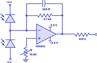
I am currently working on a high-speed transimpedance amplifier (TIA) circuit using the OPA855, and I’ve encountered unexpected oscillations at the output. I’m seeking your support to help understand the cause and to find a way to eliminate them.
Setup Description (see Picture1 for the schematic):
-
Photodiode configuration: Two photodiodes are connected in series and reverse-biased with ±5V.
-
The common cathode/anode junction is connected to the inverting input of the OPA855.
-
Standard TIA configuration with recommended feedback components.
-
Output is monitored on a high-speed oscilloscope for both DC and FFT analysis.
Observations:
-
Picture2 – With Photodiodes (No Laser Input):
-
Output FFT shows a strong oscillation at ~3.6GHz, along with its second harmonic at ~7.2GHz.
-
This is seen even without any light input to the photodiodes.
-
-
Picture3 – Without Photodiodes:
-
When the photodiodes are disconnected and the circuit is left open at the inverting input, the oscillation changes to ~2.3GHz, with multiple harmonics on the right.
-
The DC level of the output also increases significantly (pk-pk).
-
Questions:
-
What could be the root cause of these oscillations?
-
Why does the oscillation frequency shift when the photodiodes are removed?
-
Could this be due to layout issues, parasitic capacitance, or impedance mismatch at high frequency?
-
How can I mitigate or eliminate these oscillations to achieve a clean TIA output?
Any insights or suggestions would be greatly appreciated. Please let me know if further information (like layout screenshots, feedback values, or part numbers) would help with the analysis.