This thread has been locked.

If you have a related question, please click the "Ask a related question" button in the top right corner. The newly created question will be automatically linked to this question.

LMH3401: Harmonic Level Deteriorate with Low-pass Filter at the Input

Part Number: LMH3401


Tool/software:

When the LMH3401 is powered by a single power supply and VCM=0.5*supply voltage, the input and output resistances refer to the circuit diagram in the datasheet. The diagram is as follow:

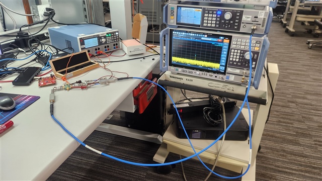
The input is single tone of -9dBm and the frequency is 800MHz from SMA100B. The output power is -4 dBm and the 2nd harmonic level is -70dBc measured by spectrum analyzer.

To reduce harmonic level of the input signal, a low-pass filter is inserted between the signal generator and FDA. The cut-off frequency of LPF is 1GHz and the insert loss is 0.5 dB at 800MHz and 40 dB at 1.6 GHz.

A strange phenomenon occurs when the LPF is added, as the harmonic level is deteriorated to -60dBc.

Why does the harmonic level of the LMH3401 deteriorate by more than 10dB when a LPF is added before the single-ended input to suppress the harmonics of the previous circuit?

Is there any methods to reduce the output harmonic level when a LPF is added?

  • Hi there,

    How is your setup here, is this connectorized LPF? Can you measure the output power of the fundamental tone of the device after the LPF is connected?

    Thanks,
    Gideon

  • 1、I can measured the output power of the fundamental tone of the device after the LPF is connected, and the power in band is correct.

    2、When using a single-ended input, it is a connectorized LPF only between the signal generator and FDA. If the same filter as the input port is added to the unused input port, the out-of-band harmonics can return to the normal state. Why is that?

  • Hey there Kelin,

    I am also measuring -60 dBc at -4 dBm fundamental output. I will have to get back to you tomorrow with reasons why this is a bit low. 

    Gideon

  • Hi there Kelin, 

    Can you comment more on your setup? are you measuring with the device EVM? Or is this on a custom board?

    Thanks

  • 1、I designed a test board powered by a single power supply myself and implemented the single-ended to differential conversion function.

    2、To suppress the second harmonic of the sma100b signal source and obtain the second harmonic of the LMH3401 itself, a low-pass filter is added between the single-ended input and the signal source output to filter out the second harmonic of the signal source.

    3、When no filter is added, the output fundamental wave is -3 DBM. The level of the second harmonic is in the table, and the value indicated in the manual was not measured. May I ask how the values in the manual can be measured?

    4、After adding a filter to one end, the second harmonic deteriorates. When the output fundamental wave is -3 DBM, the second harmonic can deteriorate to -50 dBc, which is far lower than the manual value. What is the reason for this?

  • Hi there Kelin,

    Without knowing how the board is set up, its hard to say what exactly could be causing this deterioration. It could be that the HD2 from the spectrum analyzer is causing some issues. I was initially facing this issue, and i can share what i did to get around it. 

    Pictured below is my setup:

    I have SMA100B going through 800 MHz LPF into LMH3401EVM with INM terminated through a DC block. The OUTP and OUTM go into DC blocks, 3 dB pad then into a balun, then finally into the spectrum analyzer. There is also resistors on board to aide in matching, which add another 3 dB of loss. Total loss at the output of the device is around 11.1 dB. This means that for a power of -3 dBm out of the device, i was looking for -14.1 dBm at the spectrum analyzer. 

    The spectrum analyzer required internal RF input attenuation to be increased to 31 dB to ensure its HD2 was below the DUT. I think this could be the issue you are facing. As for why the measurement was better without the LPF vs with, it could be due to some phase adding constructively/destructively from the signal generator artificially lowering the number. 

    Here are my HD2 measurements, I had to zoom into very close around the fundamental for this to keep the sweep time low: Fundamental is on the right and HD2 is on the left. 

    As you can see, I am seeing about 66 dBc of HD2 at this frequency.

    Let me know if theres anything else i can help with,

    Gideon

  • Hi Gideon

    1、The HD2 at 800MHz is around 70dBc from Figure 13 in its sheet, but your result is 66dBc. This have a significant difference, and what is the reason for this difference? How were the data in the manual tested, and could you provide a reference board circuit for the test results shown in Figure 13 of the manual?

    2、The board  seted up is the same with mine except the bulan. I test the HD2 is a little worse with LPF in input terminal than without, as shown in table. 

    3、Could you test the HD2 without LPF and with LPF at 600, 700, 800MHz for for comparision.